
Contents: Crankshaft speed sensor ⇓ Camshaft Position Sensor ⇓ Temperature sensors ⇓ Air flow meter ⇓
The electronic diesel engine control system EDC for Common Rail includes three large systems:
1. Sensors for recording operating mode parameters, which convert various material parameters into electrical signals.
2. ECU for generating output electrical signals based on signals from sensors and a given algorithm.
3. Drives for converting the ECU output electrical signals into mechanical parameters.
Crankshaft speed sensor
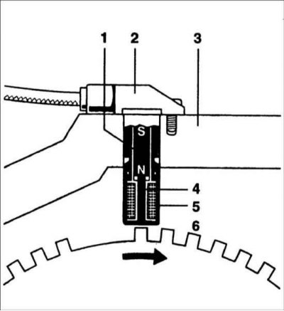
1 – permanent magnet; 2 – casing; 3 – engine crankcase; 4 – metal rod; 5 – coil; 6 – toothed rotor
The position of the piston in the engine cylinder is decisive in determining the moment of fuel injection into the combustion chamber. Since the pistons are rigidly connected to the crankshaft via connecting rods, the crankshaft position sensor transmits information to the control unit regarding the position of all pistons. The inductive speed sensor detects the rotational speed of the crankshaft, and this important input variable is transmitted to the ECU.
A ferromagnetic rotor with 60 teeth is fixed to the crankshaft, with 2 teeth missing from the rotor. This gap is located in a certain position relative to the crankshaft and the position of the piston in the first cylinder. The sensor is a permanent magnet and a metal rod with an inductive coil. When the rotor teeth pass near the sensor pole, a sinusoidal voltage is induced in it, the amplitude of which increases with increasing crankshaft rotation frequency.
Camshaft Position Sensor
The camshaft controls the intake and exhaust valves and rotates at half the speed of the crankshaft. As the piston moves toward top dead center, the position of the camshaft indicates which piston is on the compression stroke or exhaust stroke.
Information is taken from a thematic website www.hyundaibook.ru
The camshaft position sensor works on the Hall effect. A short-term signal from the sensor tells the ECU that the piston of the first cylinder has entered the compression stroke.
Temperature sensors
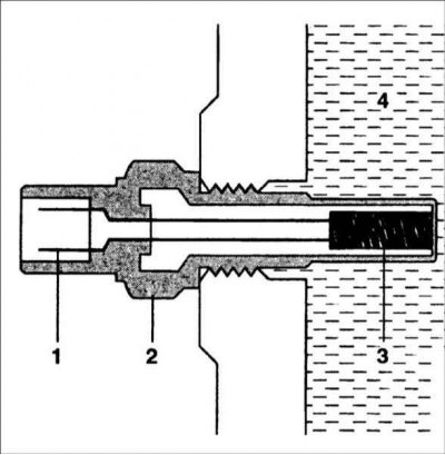
1 – connector; 2 – body; 3 – NTC resistor
Temperature sensors are installed in various places of the engine and are designed to measure the temperature of the coolant, air entering the engine, engine oil and fuel returning to the fuel tank. The core of each sensor is a resistor whose resistance changes depending on the temperature with a negative temperature coefficient (NTC). The voltage drop across the resistor is transmitted to the ECU via an analog-to-digital converter (ADC). The sensor characteristic is stored in the ECU memory as a function of voltage.
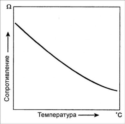
Temperature sensor characteristic (NTC)
Air flow meter
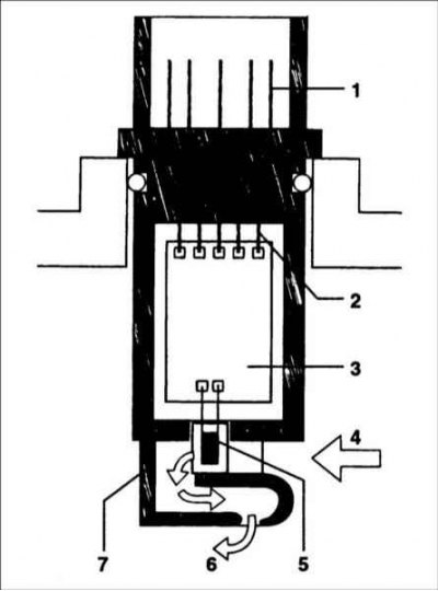
1 – connector contacts; 2 – internal connections; 3 – electronic unit; 4 – air inlet hole; 5 – sensor element; 6 – air outlet hole; 7 – body
The fuel injection system is designed to precisely dose fuel depending on the amount of incoming air under various engine operating conditions. The correct air-fuel ratio is necessary to reduce the amount of harmful substances in the exhaust gases. This requires the use of sensors that accurately record the actual air flow entering the engine cylinders at any given moment.
The accuracy of the sensor should not be affected by pulsations, the exhaust gas recirculation system and the temperature of the air entering the engine. An air flow meter with a heated thin film meets these requirements. A micromechanical measuring system records the air flow and its direction.