
Location of injection system components "Common Rail" on a diesel 4-cylinder engine
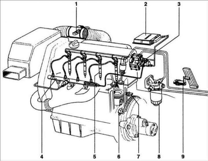
1 – air flow meter; 2 – ECU; 3 – high pressure fuel pump; 4 – high pressure accumulator; 5 – fuel injectors; 6 – crankshaft speed sensor; 7 – coolant temperature sensor; 8 – fuel filter; 9 – Fuel pedal position sensor
The main element of the fuel injection system is the fuel pump, which is installed on all diesel engines. Injection pressures of up to 1,350 bar are required to increase power to 160 kW per cylinder.
In recent years, many diesel fuel injection systems have been developed, in particular direct injection (DI). The goal was not only to increase engine power, but also to reduce fuel consumption and noise and reduce the toxicity of exhaust gases. Compared to previously used systems, the Bosch fuel injection system "Common Rail" (battery fuel system) for direct fuel injection (Dl) provides greater flexibility in adapting to the diesel engine fuel system, such as:
- wide range of applications (for passenger cars and commercial vehicles with outputs of 30 kW per cylinder, as well as for heavy-duty trucks, locomotives and ships with outputs of 200 kW per cylinder;
- high fuel injection pressures up to 1400 bar;
- injection changes when starting the engine;
- possibility of control, main and late injection;
- ensures that the injection pressure corresponds to the engine operating mode.
Functioning of the injection system
Distinctive characteristic of a common pipeline system "Common Rail" (battery fuel system) consists of separating the pressure-generating unit and the fuel injection unit.
The basis of the system is a reservoir (battery). The injection pressure does not depend on the amount of fuel injected and the engine crankshaft speed. The fuel supply under pressure is located in the high-pressure accumulator "Common Rail" and ready for injection. The amount of fuel injected is determined by the driver's request, and the injection pressure is calculated by the control unit (ECU) based on information from various sensors. At a precisely set moment, the ECU transmits an excitation signal to the injector solenoid, indicating the start of fuel delivery. The amount of fuel injected is determined by the opening period of the nozzle and the pressure in the system. The ECU and fuel injection system sensors include:
- ECU;
- crankshaft speed sensor;
- camshaft position sensor;
- accelerator pedal position sensor;
- common rail pressure sensor;
- coolant temperature sensor;
- air flow meter.
Based on information from the above sensors and driver requirements (accelerator pedal position) The ECU determines the instantaneous operating characteristics of the engine and the vehicle as a whole. The unit processes signals generated by sensors and transmitted via communication lines and, based on this information, controls the injection system in open or closed loop mode. The engine crankshaft speed is measured by the crankshaft speed sensor, and the camshaft position sensor determines the fuel injection sequence (phase length). The electrical signal from the accelerator pedal position potentiometer informs the ECU of the degree to which the driver is pressing the accelerator pedal.
The air flow meter transmits a signal to the ECU with data regarding the instantaneous air flow, which allows calculating the process of complete combustion of fuel with a minimum content of harmful substances in the exhaust gases. Since the engine is equipped with a turbocharger and boost pressure control, an additional sensor also measures this pressure. At low outside temperatures and a cold engine, the ECU determines the injection timing and other parameters corresponding to a special operating mode. Depending on the vehicle and the increased safety and comfort requirements, additional sensors may be used to transmit information to the ECU. The figure shows an example of a diesel 4-cylinder engine with a fuel injection system "Common Rail".
Attention! The shown arrangement of elements does not correspond to their actual arrangement.
Main functions
The main functions of the system are to ensure the injection of the required amount of fuel at a strictly defined moment and under the required pressure. This ensures not only smooth operation of the diesel engine, but also economical fuel consumption.
Additional functions
Additional closed-loop functions and non-feedback control functions serve to reduce exhaust gas toxicity and fuel consumption and are used to improve safety, comfort and convenience.
For example: exhaust gas recirculation (EGR), boost pressure control, gear shifting, electronic immobilizer, etc. The CAN system provides data exchange with other vehicle systems. When performing a diagnostic check on a vehicle, it is possible to retrieve data stored in the system's data reserve.