
Common Rail Fuel Injection System
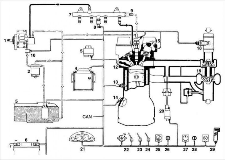
1 – high pressure fuel pump; 2 – fuel filter; 3 – fuel tank with preliminary fuel filter and fuel booster pump; 4 – ECU; 5 – glow plug control unit; 6 – battery; 7 – high pressure accumulator (rail); 8 – pressure sensor; 9 – pressure limiting valve; 10 – fuel temperature sensor; 11 – nozzle; 12 – glow plug; 13 – coolant temperature sensor; 14 – crankshaft speed sensor; 15 – camshaft position sensor; 16 – engine air temperature sensor; 17 – Boost Pressure Sensor (BPS); 18 – air flow meter; 19 – turbocharger; 20 – EGR positioner; 21 – instrument cluster; 22 – accelerator pedal position sensor; 23 – brake contacts; 24 – Clutch pedal switch; 25 – speed sensor; 26 – vehicle speed control unit; 27 – air conditioning compressor; 28 – air conditioning control unit; 29 – diagnostic tool with connector
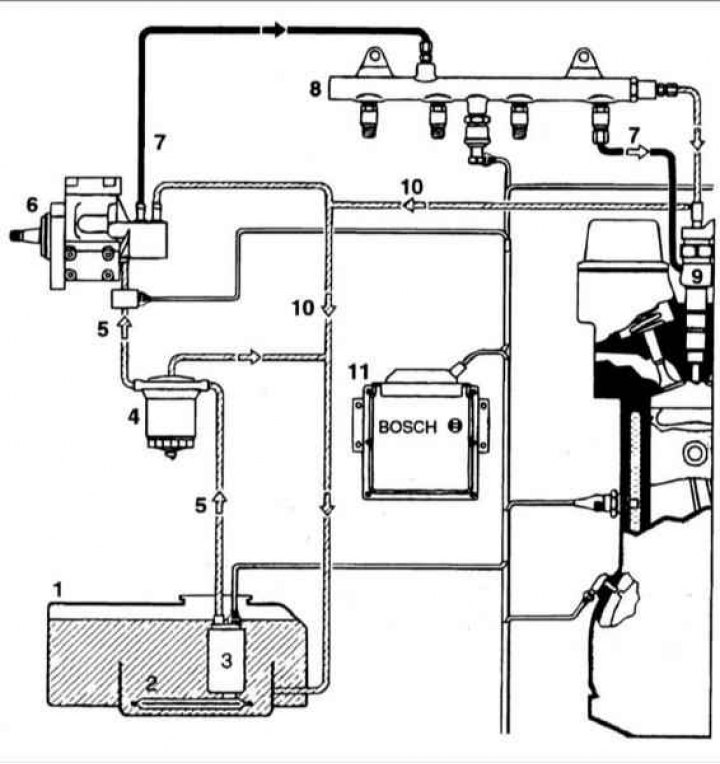
1 – fuel tank; 2 – Pre-fuel filter; 3 – fuel booster pump; 4 – fuel filter; 5 – low pressure fuel lines; 6 – high pressure fuel pump; 7 – high pressure fuel lines; 8 – high pressure accumulator (rail); 9 – electromagnetically controlled injectors screwed into the cylinder head; 10 – return fuel line; 11 – ECU
The Common Rail fuel system includes a low pressure fuel stage and a high pressure fuel stage and an ECU (11).
Low pressure fuel supply
The low pressure fuel supply of the Common Rail system includes:
- fuel tank with pre-fuel filter;
- fuel lift pump;
- fuel filter;
- low pressure fuel lines.
Fuel lift pump
An electric fuel pump with a pre-filter continuously supplies a certain amount of fuel from the fuel tank to the high-pressure fuel pump. The pump not only supplies fuel, but within the limits of the safety system, it must stop supplying fuel in the event of an accident, i.e. when the ignition is on and the engine is stopped.
The fuel pump consists of three main elements:
- pump;
- electric motor;
- lids.
Fuel filter
Insufficient fuel cleaning can cause damage to high-pressure fuel pump components, delivery valves and injector nozzles. The fuel filter cleans the fuel before it enters the high-pressure fuel pump and thus prevents premature wear in sensitive pump components.
Diesel fuel may contain water either in bound form (emulsion) or in free form (for example, condensation of water vapor when the temperature changes). If water gets into the injection system, it can lead to corrosion of the injection system components, so a warning signal is installed that turns on the indicator lamp in the instrument cluster if it is necessary to drain the water from the fuel filter.
High pressure fuel supply
The high pressure fuel supply of the Common Rail system includes:
- high pressure fuel pump with pressure regulating valve;
- high pressure fuel lines;
- high pressure accumulator (rail) with pressure sensor, pressure limiter, flow limiter, injectors;
- return fuel line.
High pressure fuel pump
High pressure fuel pump (schematic representation of a longitudinal section)
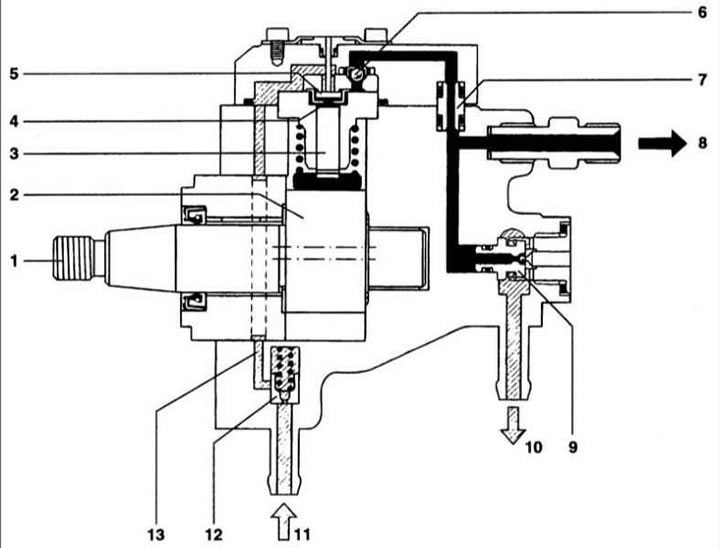
1 – drive shaft; 2 – eccentric cam; 3 – pump element with pump plunger; 4 – pump element compartment; 5 – suction valve; 6 – exhaust valve; 7 – seal; 8 – high pressure connection to the pressure accumulator; 9 – ball valve; 10 – fuel return; 11 – fuel supply from the fuel booster pump; 12 – safety valve with throttle hole; 13 – low pressure fuel supply to the pump element
High pressure fuel pump (schematic cross section)
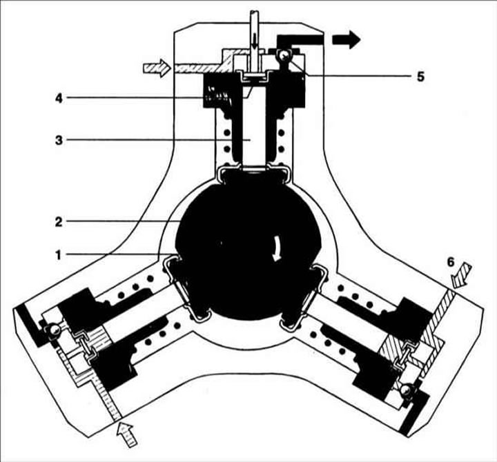
1 – drive shaft; 2 – eccentric cam; 3 – pump element with pump plunger; 4 – suction valve; 5 – exhaust valve; 6 – entrance
The high-pressure fuel pump supplies fuel at a pressure of 1350 bar to the high-pressure accumulator via high-pressure fuel lines.
The high-pressure fuel pump is located at the boundary of the low and high fuel pressure stages. Under all operating conditions, the service life of the fuel pump corresponds to the service life of the vehicle.
The fuel pump is lubricated with diesel fuel. The fuel is compressed by three pistons installed radially at an angle of 120° to each other. The pump delivers three portions of fuel per one revolution of the crankshaft. For a 2.0 l diesel engine operating at rated crankshaft speed and generating a pressure of 1350 bar, a power of 3.8 kW is required to drive the pump, taking into account a mechanical efficiency of approximately 90%.
Pump operation
The fuel lift pump delivers fuel through a filter with a water separator to the inlet and relief valve of the high-pressure fuel pump. Fuel through the throttle opening of the safety valve lubricates the moving elements of the pump and also cools it. The drive shaft with eccentric cams moves the three pump plungers up and down according to the shape of the cam. As soon as the supply pressure exceeds the opening pressure of the relief valve (0.5... 1.5 bar), the booster pump forces the fuel through the inlet valve of the high-pressure fuel pump into the compartment of the pump element, the piston of which moves downwards (intake stroke). The inlet valve closes when the pump piston passes BDC and, since the fuel cannot flow out of the pump element compartment, it is compressed regardless of the supply pressure.
The increasing pressure opens the outlet valve and, as soon as the pressure equal to the accumulator pressure is reached, the compressed fuel enters the high-pressure circuit. The pump piston continues to deliver fuel until it reaches TDC (injection stroke), after which the pressure decreases and the outlet valve closes. The fuel remaining in the pump element compartment expands and the pump piston moves downward. As soon as the pressure in the pump element compartment decreases below the pressure created by the booster pump, the inlet valve opens and the process repeats.
Since the pump capacity exceeds the engine fuel consumption, excess fuel under high pressure returns to the fuel tank through the pressure regulating valve. This results in unnecessary heating of the fuel and a reduction in overall efficiency.
High pressure accumulator (rail)
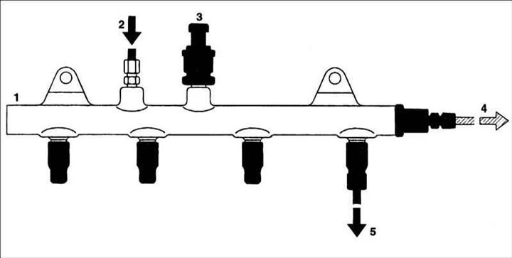
1 – high pressure accumulator; 2 – input from high pressure fuel pump; 3 – accumulator pressure sensor; 4 – return fuel to the fuel tank; 5 – to the fuel injector
The pressure generated by the high pressure fuel pump is distributed through the accumulator and fuel lines to the injector. At the same time, due to the volume of fuel in the accumulator, the fluctuations in fuel pressure created by the high-pressure fuel pump and opening injectors are reduced. The compressibility of the fuel as a result of high pressure is used to achieve the accumulator effect. The fuel pressure is measured by a sensor and maintained at the required level by a pressure regulating valve.
High pressure fuel lines
High pressure fuel lines are designed to transfer fuel from the high pressure accumulator to the injectors and must withstand high frequency pressure fluctuations that occur during engine operation. The fuel lines are made of steel and have an outer diameter of 6 mm and an inner diameter of 2.4 mm. All high-pressure fuel lines must be of the same length. The difference in distance between the battery and each fuel injector is compensated by bending the fuel lines.
Pressure sensor
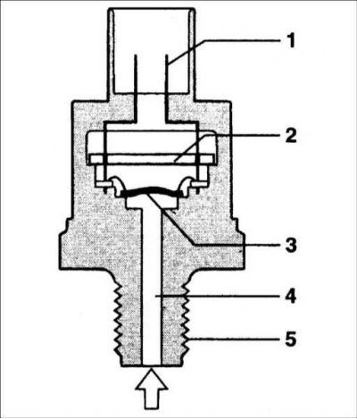
1 – electrical contacts; 2 – printed circuit board and circuit outline; 3 – diaphragm with sensor element; 4 – high pressure connection; 5 – sensor thread
The pressure sensor transmits a signal to the ECU, which corresponds to the actual pressure in the pressure accumulator.
The pressure sensor consists of the following elements:
- a combined sensor element welded to the housing;
- printed circuit board with electrical circuit;
- sensor housing with electrical connector.
Fuel under pressure through the hole acts on the sensor diaphragm, on which the sensor element is installed (semiconductor device) converting pressure into an electrical signal. The generated and amplified signal is transmitted to the ECU via the connector contacts and the electrical circuit. The sensor works as follows: when the shape of the diaphragm changes, the electrical resistance of the layers glued to the diaphragm changes. A pressure change of 1500 bar results in a change in the shape of the diaphragm by 1 mm.
Depending on the applied pressure, the sensor output voltage varies from 0 to 70 mV and after amplification is 0.5–4.5 V. Accurate measurement of accumulator pressure is necessary for the correct functioning of the fuel injection system. In the working range, the measuring accuracy should be within ±2%. If the pressure sensor fails, the pressure control valve switches to the "diaphragm" mode and the injection system, using the reserve (soft) function, accepts a preset pressure value.
Pressure relief valve
The pressure limiting valve performs the same function as the excess pressure valve. In case of excess pressure, the valve opens and limits the pressure in the accumulator. The opening pressure of the pressure limiting valve is 1500 bar.
The pressure limiting valve is a mechanical device that includes the following elements:
- body with external thread for screwing into a pressure accumulator;
- connection of the fuel return pipe to the fuel tank;
- movable plunger;
- spring.
Nozzles
Nozzle: A – nozzle closed (motionless state); B – the nozzle is open (fuel injection)
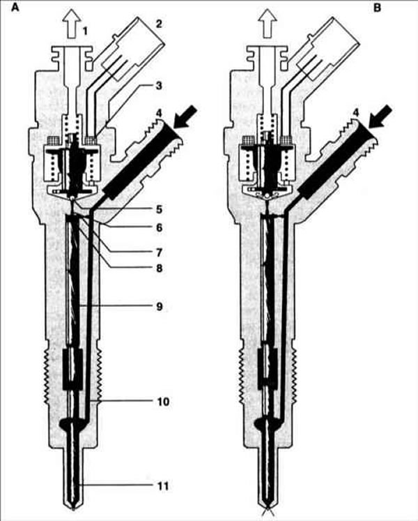
1 – fuel return 2 – electrical connector 3 – starting element (solenoid valve) 4 – Fuel inlet from pressure accumulator 5 – Ball valve 6 – Leak hole 7 – Feed hole 8 – Valve control section 9 – Valve control plunger 10 – Fuel supply channel to atomizer 11 – Injector needle
The injector ensures that the required amount of fuel is supplied to the combustion chamber. At a precisely set moment, the ECU transmits an excitation signal to the injector solenoid, which means the fuel supply has started. The amount of fuel injected is determined by the opening period of the nozzle and the pressure in the system. The fuel returning from the pressure regulating valve and the low pressure stage is fed into the manifold together with the fuel that lubricated the high pressure fuel pump.
The injector consists of the following units:
- sprayer;
- hydraulic system;
- solenoid valve.
Fuel is supplied from the high pressure threaded connection through the channel to the atomizer and through the supply hole to the valve control compartment. The valve control section is connected to the fuel return line through a leak hole connected to the solenoid valve. When the leak hole is closed, the hydraulic force applied to the valve control plunger exceeds the force from the pressure on the conical end of the spray needle. As a result, the nozzle needle moves down and hermetically closes the supply of high-pressure fuel to the combustion chamber.
When the injector solenoid valve opens, the leak hole is opened, which causes the pressure in the valve control compartment to decrease, which also reduces the hydraulic pressure on the plunger. As soon as the hydraulic force becomes lower than the force from the pressure on the conical end of the nozzle needle, the nozzle needle opens and fuel is injected into the combustion chamber. This indirect control of the spray needle using a hydraulic force multiplication system is used because the forces required to quickly open the needle cannot be generated directly by the solenoid valve. The so-called control amount of fuel required to open the injector needle is supplied in addition to the amount of fuel that must actually be injected into the cylinder, and it is supplied through a leakage hole connected to the solenoid valve into the return fuel line.
In addition to the amount of fuel to control, there is also fuel loss in the valve lifter guides and the injector needle.
The operation of the injector during engine operation and the creation of pressure by the high-pressure fuel pump is divided into the following four stages:
- the nozzle is closed (with the application of high pressure);
- the nozzle opens (start of fuel injection);
- the nozzle is fully open;
- nozzle closing (end of fuel injection).
When the engine is off and there is no pressure in the pressure accumulator, the spray spring closes the nozzle.
The nozzle is closed
In the stationary state, the injector solenoid valve is not energized and is therefore closed. The leak hole is closed and the valve spring presses the ball against the leak hole seat. High pressure from the pressure accumulator increases in the valve control compartment and is simultaneously present in the volume of the spray needle compartment. The pressure from the pressure accumulator applied to the end face of the control plunger, together with the force of the spray needle spring, holds the needle in the closed position, counteracting the opening forces applied in the pressure stage.
The nozzle opens
The nozzle is in a stationary position. The solenoid valve is energized by a current, which ensures that the valve opens quickly. Immediately, the high current supplied to the solenoid is reduced to a current sufficient to hold the solenoid valve open. When the leak hole opens, fuel flows from the valve control compartment into the cavity located above the valve and from there through the return line into the fuel tank.
The force created by the solenoid exceeds the spring force and the leak hole opens, which causes the pressure in the valve control compartment to decrease, which also reduces the hydraulic pressure on the plunger. As soon as the hydraulic force becomes lower than the force from the pressure on the conical end of the nozzle needle, the nozzle needle opens and fuel is injected into the combustion chamber.
The opening speed of the spray needle is determined by the difference in flow velocity through the leak hole and the feed hole. The control plunger reaches the upper position where there is a fuel cushion formed by the fuel flow between the fuel leak and feed holes. In this position, the injector nozzle is fully open and fuel is injected into the combustion chamber under a pressure equal to the pressure in the pressure accumulator.
Closing the nozzle
When the voltage to the solenoid valve is removed, the valve spring moves the armature downward and the ball closes the leak hole. The anchor consists of two parts. However, even though the armature plate is controlled by the shoulder as it moves downwards, it can "spring back" with the return spring so that no downward forces are exerted on the armature and ball.
When the leak hole is closed, the hydraulic force applied to the valve control plunger exceeds the force from the pressure on the conical end of the spray needle. As a result, the nozzle needle moves down and hermetically closes the supply of high-pressure fuel to the combustion chamber. The speed of the spray needle is determined by the flow through the feed hole.