HyundaiBook.ru
Repair Chevrolet Repair Honda Repair Toyota Repair Land Rover Repair VAZ Repair Renault Repair Nissan
English Русский
Български
Беларускі
Український
Српски
Hrvatski
Română
Polski
Slovenský
Magyar
ArticlesSitemapContacts  


  Accent   Elantra   Getz   Grandeur   Sonata   Santa Fe   Tucson   Others
Elantra 1 (1990-1995, petrol) Elantra 2 (1995-2000, petrol) Elantra 3 (2000-2006)
  • Main
  • Elantra
  • XD (2000-2006)
  • Power unit
  • Fuel system (diesel)
  • Injection system characteristics

Injection system characteristics (Hyundai Elantra XD)

0
Contents: Characteristics of a conventional…⇓ Injection system characteristics…⇓

Characteristics of a conventional injection system


In conventional fuel injection systems with a distributor and direct injection pump, the injection system includes only the main injection phase - without pilot and late injection. In the electromagnetically controlled fuel distribution pump, the actions occur as the fuel injection control phase approaches. In conventional systems, the operations of creating pressure and adjusting the amount of fuel injected are linked to each other by the interaction of the cam and plunger of the fuel pump. This has the following effects on fuel injection characteristics:
  • injection pressure increases with increasing speed and the amount of air entering the engine;
  • during the actual injection process, the injection pressure increases and then decreases to the final injection pressure.

As a result, the following consequences occur:
  • a smaller amount of fuel is injected at a lower pressure than the amount of air entering the engine;
  • peak pressure is more than double the average injection pressure;
  • in accordance with the requirements for efficient combustion, the discharge rate curve is actually triangular.

Peak pressure is decisive for the mechanical load of the fuel pump elements and its drive. In conventional fuel injection systems, this is decisive for the quality of mixture formation in the combustion chamber.

Unloading rate curve for a conventional…

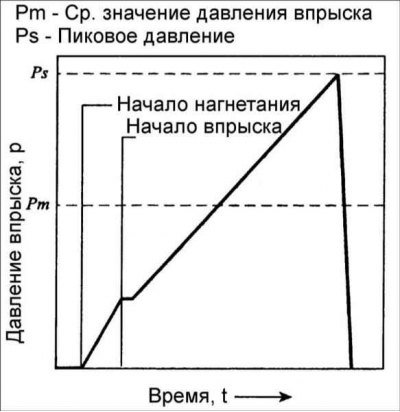
Unloading rate curve for a conventional fuel injection system


Injection system characteristics "Common Rail" (battery fuel system)


Compared with conventional injection systems, the following requirements must be met to achieve ideal injection characteristics:
  • for each operating mode of the engine, it is necessary to separate the pressure-generating unit and the fuel injection unit;
  • at the initial moment of injection, the amount of fuel injected should be as low as possible (i.e. the inertia between the initial moment of injection and the start of ignition must be taken into account).

These requirements are met by the injection system "Common Rail" – battery fuel system – with its control and main injection phases.

"Common Rail" is a block system and, in essence, the following units are responsible for the fuel injection characteristics:
  • electromagnetically controlled injectors screwed into the cylinder head;
  • high pressure accumulator (rail);
  • high pressure fuel pump.

Unloading rate curve for fuel injection…

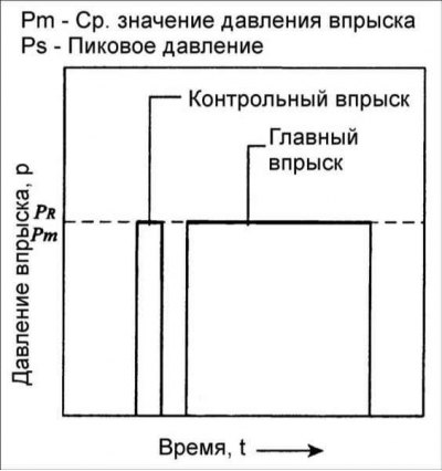
Unloading rate curve for fuel injection system "Common Rail"


The following nodes are also required for the system to function:
  • electronic monitoring device ECU;
  • crankshaft speed sensor;
  • camshaft position sensor (phase sensor).

In passenger cars, a high-pressure radial piston pump is used to create pressure, and the pressure is created independently of the fuel injection process. The pump performance is directly proportional to the engine crankshaft speed. Compared to conventional injection systems, the actual fuel injection is uniform, i.e. in Common Rail the high-pressure fuel pump is not only smaller in size, but its drive is also less susceptible to peak loads.


The fuel injectors are connected to the rail by short lines and essentially turn on the nozzles and a solenoid valve controlled by the ECU. Once the solenoid valve is de-energized, fuel injection stops. Assuming constant pressure, the amount of fuel injected is directly proportional to the length of time the solenoid valve is open. This process is completely independent of the engine crankshaft speed and the pump speed (fuel injection depending on time).

High speed switching of the solenoid is achieved by using high voltage and current. This means that a specially designed solenoid valve must be used to provide a pad when opening. The injection timing is determined by the EDC (Electronic Diesel Control) control system, which uses the crankshaft speed sensor and the camshaft position sensor to phase-determine the working cycle.
This article is available at russian, bulgarian, belarusian, ukrainian, serbian, croatian, romanian, polish, slovak, hungarian
This article has been reviewed by: Konstantin Smirnov
Add to social network:

Previous
Elantra 3: Fuel system (diesel)
Next

General information about the Common Rail injection system
Technical data of the fuel system
Controlled fuel injection
Main fuel injection
Additional fuel injection
Reducing toxicity of exhaust gases
Common Rail Fuel System
We recommend other articles on the topic of Hyundai manuals:

Technical characteristics of the cooling system Hyundai Accent 1 (1994-1999)
MFI fuel injection system Hyundai Getz (2002-2011)
Twin Cam Engine — Fuel Injection System Component Locations Hyundai Sonata 3 (1993-1998)
Distributed fuel injection system Hyundai Santa Fe 2 (2007-2012, petrol)
Characteristics of the fuel system of gasoline engines (G4GC,… Hyundai Tucson 1 (2005-2010)
Table 2.15. Technical characteristics of the control system Hyundai Matrix (2001-2010, petrol)

Link in different formats to this article

Visitor comments
No comments yet


How much will 14 + 46 ?


Elantra 3 (2000-2006) 
  • User manual
  • Control devices
  • Audio system
  • Starting the engine and driving
  • Faults en route
  • Maintenance and care
  • Technical information
  • Power unit
  • Gasoline engines
  • Diesel engines
  • Lubrication system
  • Cooling system
  • Fuel system (gasoline)
  • Fuel system (diesel)
  • Decreased toxicity
  • Ignition system
  • Transmission
  • Clutch
  • Mechanical gearbox
  • Automatic gearbox
  • Drive shafts and axles
  • Chassis
  • Car suspension
  • Steering
  • Brake system
  • Body
  • Exterior (external elements)
  • Interior (internal elements)
  • Air conditioning system
  • Electrical equipment
  • Equipment and devices
  • Headlights and lighting
  • Power devices
  • Electrical circuits
Elantra 2 (1995-2000, petrol) 
  • General information
  • Maintenance
  • Power unit
  • Engine repair
  • Cooling system
  • Intake and exhaust system
  • Fuel system
  • Transmission
  • Clutch
  • Manual gearbox
  • Automatic gearbox
  • Drive shafts and axles
  • Chassis
  • Front suspension
  • Rear suspension
  • Steering
  • Brake system
  • Body
  • Body elements
  • Electrical equipment
  • Equipment and devices
  • Electrical diagrams
Elantra 1 (1990-1995, petrol) 
  • General information
  • Introduction to the guide
  • Maintenance
  • Power unit
  • Minor engine repair
  • Engine overhaul
  • Lubrication system
  • Cooling system
  • Fuel injection system
  • Ignition system
  • Exhaust system
  • Transmission
  • Clutch
  • Manual gearbox
  • Automatic gearbox
  • Drive shafts
  • Chassis
  • Front suspension
  • Rear suspension
  • Steering
  • Wheels and tires
  • Troubleshooting
  • Brake system
  • Body
  • Body elements
  • Electrical equipment
  • Equipment and devices
  • Power devices
  • Heating and air conditioning
  • Electrical circuits
HyundaiBook.ru © 2018-2026 · Mobile version · Sitemap: EN BG BY UA RS HR RO PL SK HU · Administration · Site search · Hyundai owners Accent 1 · Accent 2 · Accent 3 · Elantra 1 · Elantra 2 · Elantra 3 · Getz · Sonata 3 · Sonata 4 · Santa Fe 2 · Tucson 1 · Tucson 2 · Matrix ·
This site uses cookies to optimize its functionality. By continuing, you agree to our terms.