
Contents: Non-TCL models ⇓ Models with TCL ⇓
Non-TCL models
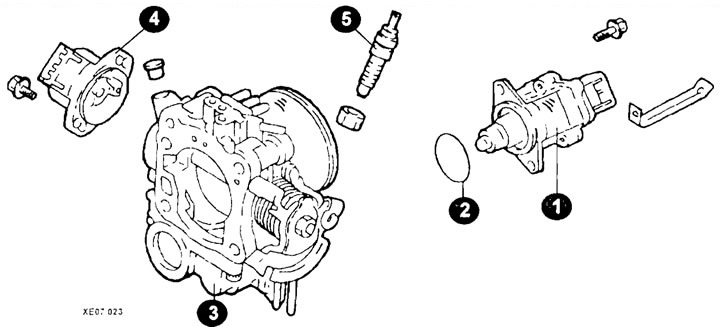
Throttle body components
1 - idle speed controller housing;
2 - gasket;
3 - throttle body;
4 - throttle position sensor;
5 - idle speed controller.
Disassembly
Remove the throttle position sensor (4) by unscrewing the bolts (see picture).
Unscrew the screws and remove the idle speed control housing (1).
Remove the damper gasket (2).
Remove the factory idle speed adjustment screw (5) from the throttle body.
Note: The screw position is adjusted at the factory.
Clean all throttle body parts.
Check for deposits in the vacuum passage or fitting. Blow them out with compressed air.
Assembly
Assembly is carried out in reverse order, taking into account the following:
Install the throttle position sensor (1).
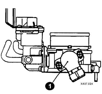
Connect a multimeter between terminal 1 and terminal 2 of the throttle position sensor connector and check that the resistance gradually increases as the throttle valve is slowly opened.
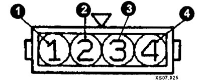
Throttle Position Sensor Connector
1 - Throttle Position Sensor - Power Supply;
2 - throttle position sensor - output signal;
3 - throttle valve closed position sensor switch;
4 - mass.
Check the circuit between terminal 3 and terminal 4 with the throttle fully closed and fully open.
If the circuit is open when the throttle valve is fully closed, turn the throttle position sensor housing counterclockwise and repeat the test.
If faulty, replace the throttle position sensor.
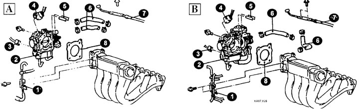
Throttle body mounting elements
1 - vacuum tube;
2 - throttle body;
3 - idle speed control connector;
4 - throttle position sensor connector;
5 - vacuum tube;
6 - connection pipe;
7 - gas pedal cable connection (accelerator);
8 - gasket;
A - models without TCL;
B - models with TCL.
Models with TCL
Disassembly
Loosen the clamp and remove the cooling system hose.
[The original text is located on the portal HYUNDAIBOOK.ru]
After unscrewing the bolts, remove the throttle position sensor.
After unscrewing the bolts, remove the gas pedal position sensor (accelerator).
After unscrewing the bolts, remove the lever assembly.
Remove the idle speed control valve housing assembly and gasket.
Remove the factory idle speed adjustment screw.
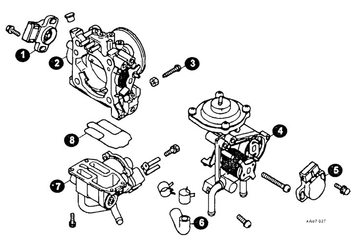
Throttle body components
1 - throttle position sensor;
2 - throttle body;
3 - idle speed adjustment screw;
4 - growl together;
5 - gas pedal position sensor (accelerator);
6 - cooling system hose;
7 - idle speed controller;
8 - gasket.
Assembly
Assembly is carried out in reverse order, taking into account the following:
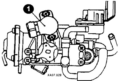
Install the gas pedal position sensor (accelerator) (1) as shown in the figure and tighten the screws that secure it.
Connect a multimeter between terminals 3 and 4 of the gas pedal position sensor connector (accelerator) and check that when the throttle valve is opened slowly (until it is fully opened), the resistance gradually increased.
Check the circuit between terminal 2 and terminal 1. When the throttle is fully closed, the circuit should be closed, and when the throttle is open, the circuit should be open.
If the circuit is open when the throttle valve is fully closed, then turn the gas pedal position sensor housing (accelerator) clockwise and check again.
If there is a malfunction in the sensor, replace the gas pedal position sensor (accelerator).
Install the throttle position sensor (see description of models without TCL).
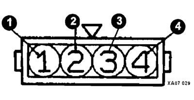
Accelerator pedal position sensor connector (accelerator)
1 - mass;
2 - throttle position sensor;
3 - power supply for the gas pedal position sensor;
4 - output signal of the gas pedal position sensor.