
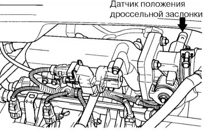
Fig. 2.244. Throttle position sensor
The throttle position sensor is shown in Fig. 2.244.
The throttle position sensor is mounted on the side of the throttle body, the movable part of the sensor is connected to the throttle axis. The sensor is designed as a variable resistor (potentiometer), the resistance of which changes depending on the position of the throttle valve. When the valve opens, the resistance of the sensor decreases, and when it closes, it increases. The engine control unit supplies a reference voltage to the sensor and measures the voltage in the signal circuit of the sensor. The ECU uses information from the throttle position sensor to regulate the ignition timing and fuel injection duration. Based on signals from the throttle position sensor and the mass air flow sensor, the ECU calculates the engine load.
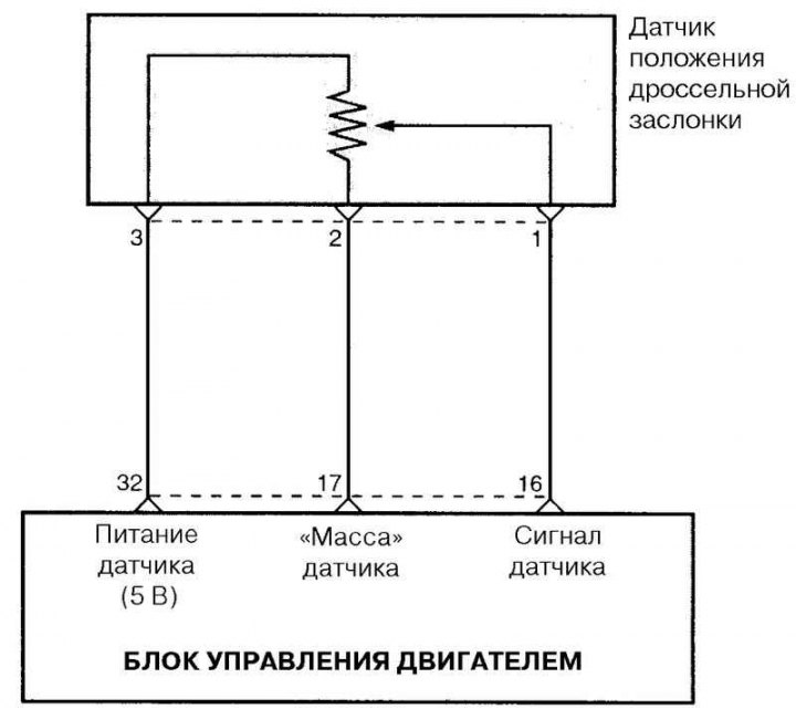
Fig. 2.245. Connection diagram of the throttle position sensor with the ECU
Conditions for storing fault codes
The ECU stores P0121 in memory and turns on the engine management system malfunction indicator lamp if there is a mismatch between the engine load signal from the throttle position sensor and the signal from the absolute pressure sensor. This code indicates that the throttle position and air flow information sent to the ECU from the throttle position sensor and the absolute pressure sensor does not match the actual engine load.
The ECU stores code P0122 and illuminates the engine management indicator lamp if the throttle angle is less than 2.1° for more than 0.2 seconds in two driving cycles. This code indicates that the throttle position sensor or the ECU detects an unusually small throttle angle. The ECU stores code P0123 and illuminates the engine management indicator lamp if the throttle angle is greater than 105.4° for 0.2 seconds in two driving cycles. This code indicates that the throttle position sensor or the ECU detects an unusually large throttle angle.
Note: The nominal resistance value when measured at terminals 1 and 3 of the throttle position sensor is within the range of 1600–2500 Ohms.
Examination
Disconnect the throttle position sensor electrical connector.
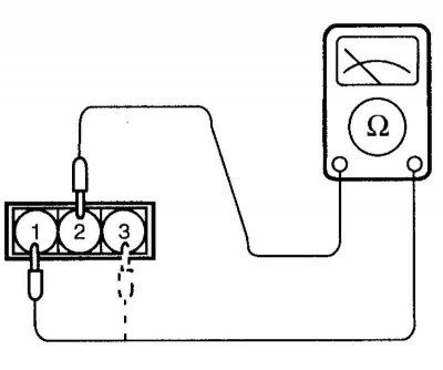
Fig. 2.246. Connection diagram for checking the throttle position sensor
Check the resistance at terminals 2 (sensor ground) and 3 (sensor power supply) of the sensor electrical connector (Fig. 2.246).
Nominal resistance value: 0.7–3.0 kOhm
Connect an analog ohmmeter to terminals 2 (sensor ground) and 1 (sensor signal) of the sensor electrical connector.
Slowly move the throttle valve from the idle position to the fully open position, watch for a smooth change in resistance proportional to the opening angle of the valve.
If the resistance deviates from the norm or changes unevenly, replace the throttle position sensor.
Tightening torque of the throttle position sensor: 1.5–2.5 N·m.
The original text is located on the portal: www.HyundaiBook.ru