


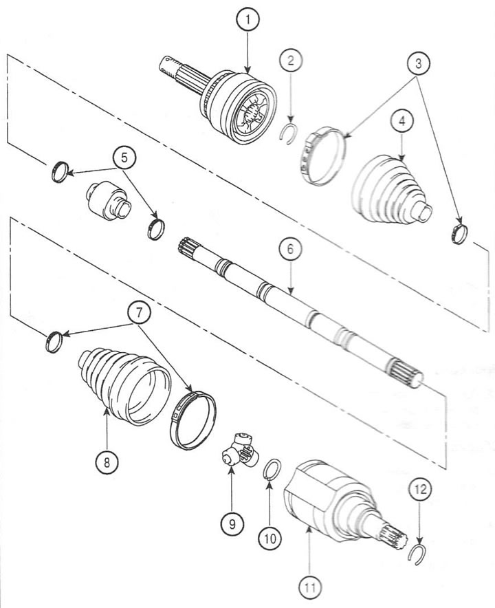
1. External hinge; 2. Retaining ring; 3. Clamp; 4. Dust cover; 5. Dynamic damper clamp; 6. Drive shaft; 7. Clamp; 8. Dust cover; 9. Crosspiece; 10. Retaining ring; 11. Inner hinge; 12. Retaining ring
Disassembly
Note: The outer joint of the drive shaft cannot be disassembled.
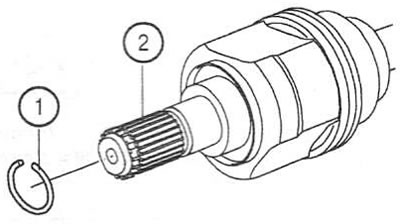
1. Remove the retaining ring (1) from the inner joint (2).
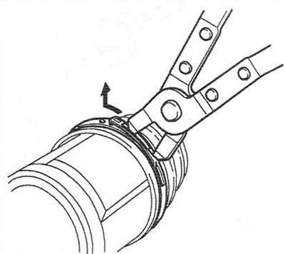
2. Remove the inner joint boot clamps.
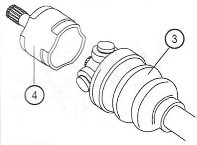
3. Remove the boot (3) and the inner joint housing (4).
Caution: Before removing the housing (5) and tripod (6) from the drive shaft (7), apply assembly marks (8) to them.
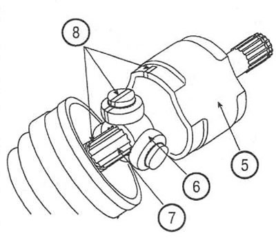
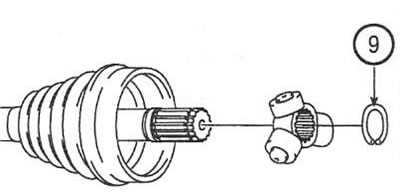
4. Using a flat-head screwdriver, remove the retaining ring (9).
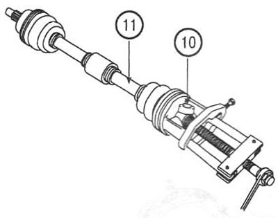
5. Using a suitable puller, remove the tripod (10) from the drive shaft (11).
6. Clean the tripod and shaft splines from grease.
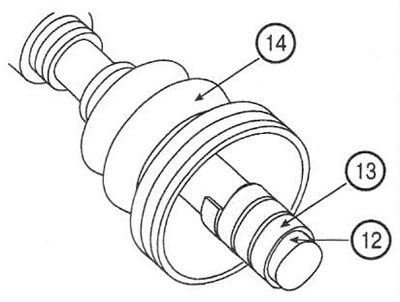
7. Wrap the splines of the drive shaft (12) with adhesive tape (13) and remove the boot (14) of the inner joint.
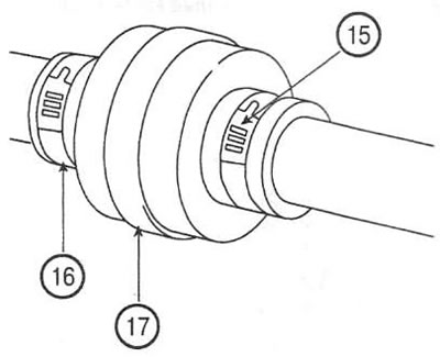
8. Remove the clamps (15 and 16) and the dynamic damper (17).
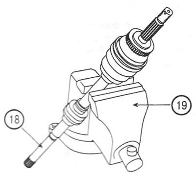
9. Clamp the drive shaft (18) in a vice (19) as shown.
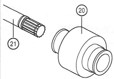
10. Remove the dynamic damper (20) from the drive shaft (21).
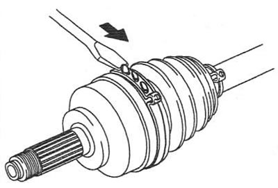
11. Remove the clamp and pull off the outer joint boot.
Examination
12. Check the drive shaft splines, crosspiece and rollers for wear, damage or corrosion.
Assembly
13. Wrap the drive shaft splines with tape to avoid damaging the dust boots.
14. Apply grease to the outer joint boot and install it.
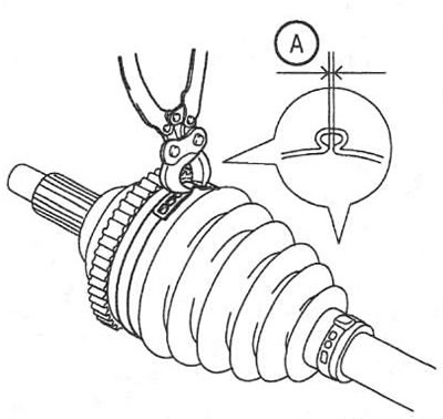
15. Install the outer joint boot clamp. Clearance A: 2.0 mm or less.
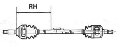
16. Install the dynamic damper as shown and secure it with clamps. RH distance: 405±3 mm.
17. Install the inner joint boot and clamp.
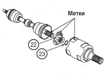
18. Align the marks and install the tripod (22), retaining ring (23) and hinge housing.
19. Apply the same amount of grease to the joint boot as was removed during disassembly.
20. Install the dust boots and secure them with clamps. To ensure proper air distribution in the joint, ensure that the appropriate distance is maintained between the dust boot clamps. Nominal value: 504.1±2 mm (left shaft); 792.0±12 mm (right shaft).