


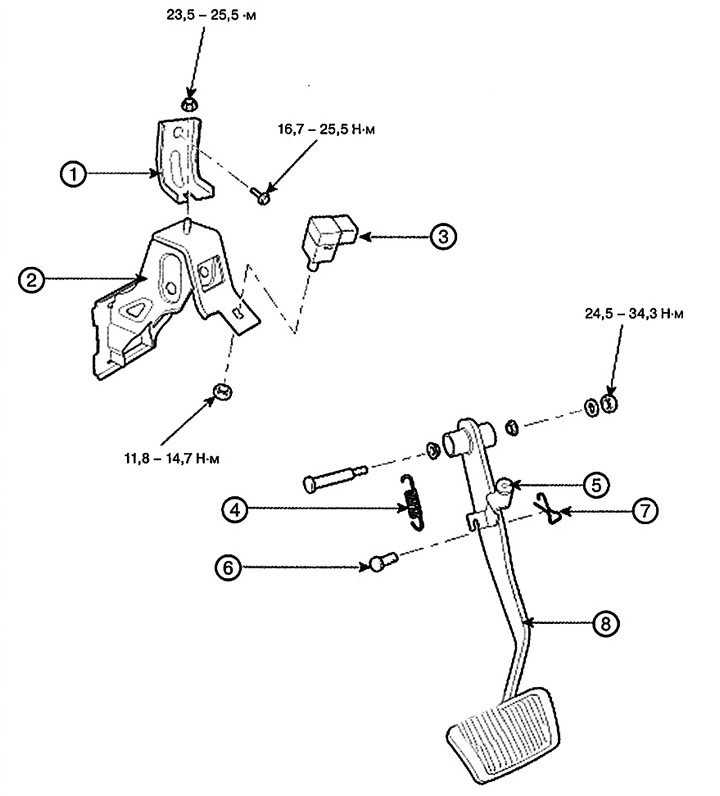
1. Bracket
2. Pedal support
3. Brake light switch
4. Return spring
5. Limiter
6. Finger
7. Cotter pin
8. Brake pedal
Removal
1. Remove the lower part of the instrument panel.
2. Pull down the steering column shaft, having first unscrewed the bolts and nuts.
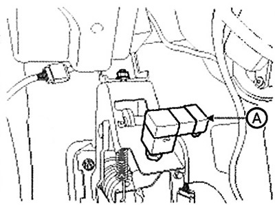
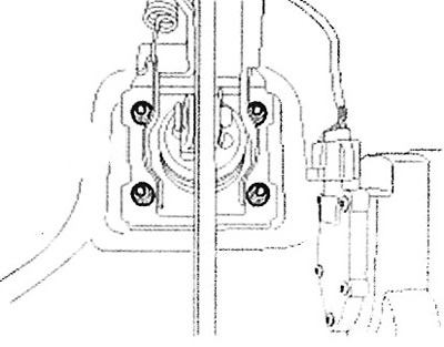
3. Disconnect the brake light switch connector (A).
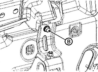
4. Loosen the nuts (B) securing the brake pedal support.
Note: Tightening torque: 16.7-25.5 Nm.
5. Remove the cotter pin (A) and then the pin (B).
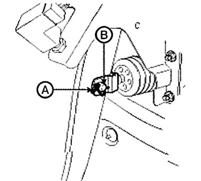
6. Loosen the brake pedal mounting nuts, then remove the brake pedal assembly.
Note: Tightening torque: 16.7-25.5 Nm
Checking the technical condition
1. Check the bushing for wear.
2. Check the brake pedal for bending or twisting.
3. Check the brake pedal return spring for damage.
4. Check the brake light switch.
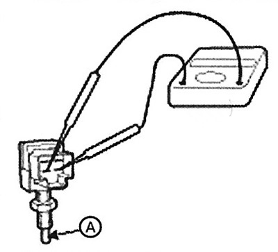
(1) Connect a circuit tester to the brake light switch connector and check for continuity with the plunger pressed and released.
(2) The brake light switch is in good condition if there is no continuity when the rod (A) is pressed.
Adjustment
Pedal height and free travel
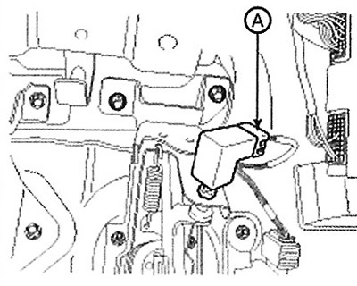
1. Disconnect the connector (A) and loosen the stop light switch lock nut.
2. Adjust the height (A) of the brake pedal as shown in the figure below.
Note: Pedal height (A): 165 mm. Full stroke: 135 mm.
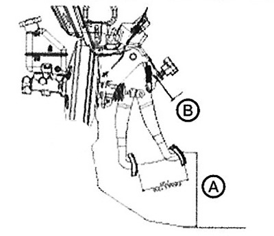
3. Adjust the clearance (B) of the brake light switch and the free play of the brake pedal.
Note:
- Brake light switch gap (B): 1.5 - 2.0 mm.
- Pedal free travel: 3.0 - 8.0 mm.
4. Connect the brake light switch connector.
Installation
1. Installation is carried out in reverse order.
Attention.
- Apply grease to the pin before installing it.
- Always install a new cotter pin.
2. Adjust the brake pedal height and free travel.
3. Check the operation of the brake pedal.