Note: This operation does not require removing the engine from the vehicle.
Note:
- 1. To avoid incorrect connections during installation, mark all connectors and hoses when disconnecting them.
- 2. Check drive belts before removing the cylinder head.
- 3. Turn the crankshaft so that the piston of the first cylinder is at the top dead center of the compression stroke.
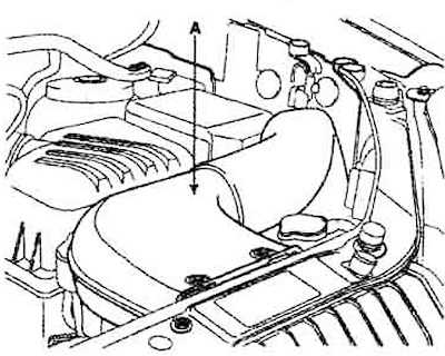
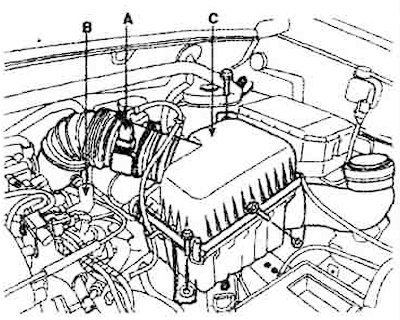
1. Remove the air intake (A).
2. Disconnect the negative terminal from the battery.
3. Unscrew the radiator cap and the drain plug of the cooling system and drain the coolant.
4. Remove the engine cover.
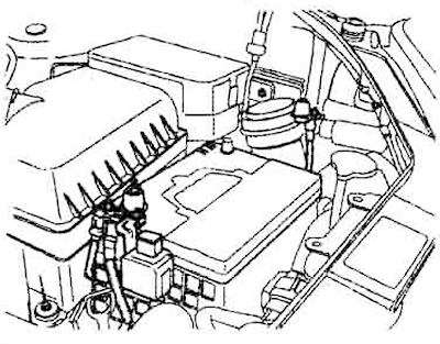
5. Disconnect the MAF sensor connector (A) and breather hose (B). Remove the air cleaner (C) complete with intake hose.
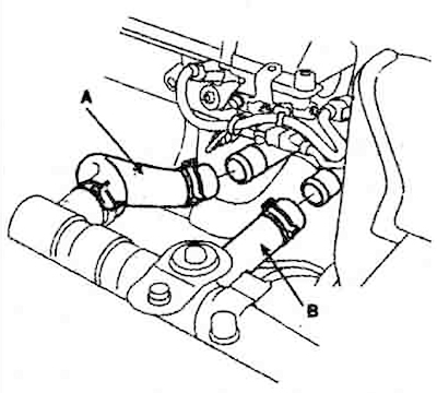
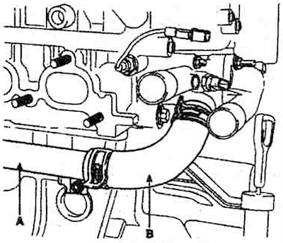
6. Disconnect the upper (A) and lower (B) radiator hoses.
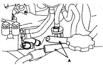
7. Disconnect the heater hoses (A).
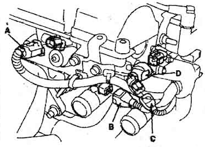
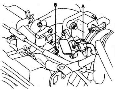
8. Disconnect the connectors on the cylinder head and intake manifold:
- 1) A - phase shifter dispenser connector;
- 2) B - oil temperature sensor connector;
- 3) C - coolant temperature sensor connector;
- 4) D - ignition coil connector;
- 5) A - throttle position sensor connector;
- 6) B - idle speed control connector;
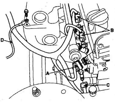
- 7) A - camshaft position sensor connector;
- 8) B - four fuel injector connectors;
- 9) C- knock sensor connector
- 10) D - ground cable.
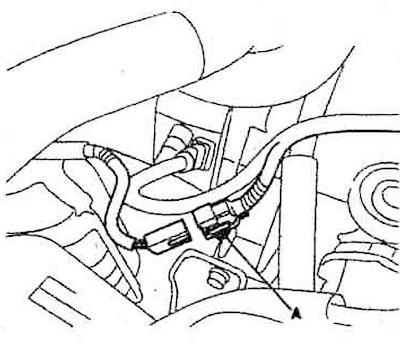
- 11) A - oxygen sensor (lambda probe) connector.
12) A - solenoid valve connector.
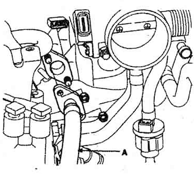
9. Disconnect the fuel hose (A) from the line.
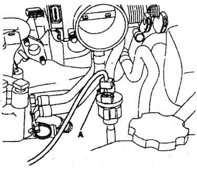
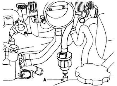
10. Disconnect the solenoid valve hose (A).
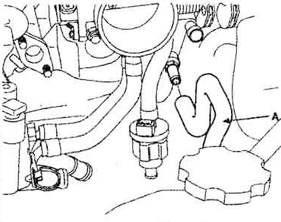
11. Disconnect the hose (A) from the brake booster.
12. Loosen the lock nuts and remove the throttle cable.
13. Remove the power steering pump.
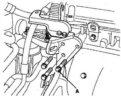
14. Loosen the mounting bolts (A) of the power steering pump bracket.
15. Disconnect the high-voltage wires from the spark plugs.
16. Disconnect the crankcase ventilation hose.
17. Remove the cylinder head cover.
18. Remove the drive belt.
19. Remove the exhaust manifold.
20. Remove the intake manifold.
21. Remove the camshaft gear.
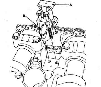
22. Secure the camshaft chain tensioner (A) with the lock (B). Remove the camshaft chain tensioner (A).
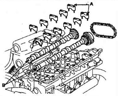
23. Remove the camshaft main bearing caps (A) and camshafts (B).
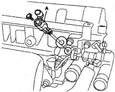
24. Remove the phase shifter dispenser (A).
25. Remove the phase shifter metering filter (A).
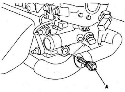
26. Disconnect the water hose (B) from the pipe (A).
27. Using a wrench (10 mm), first loosen and then remove the cylinder head mounting bolts in the order shown in the figure.
28. Remove the cylinder heads from the guide pins and place them on wooden blocks.