
Fragment of electrical equipment diagram
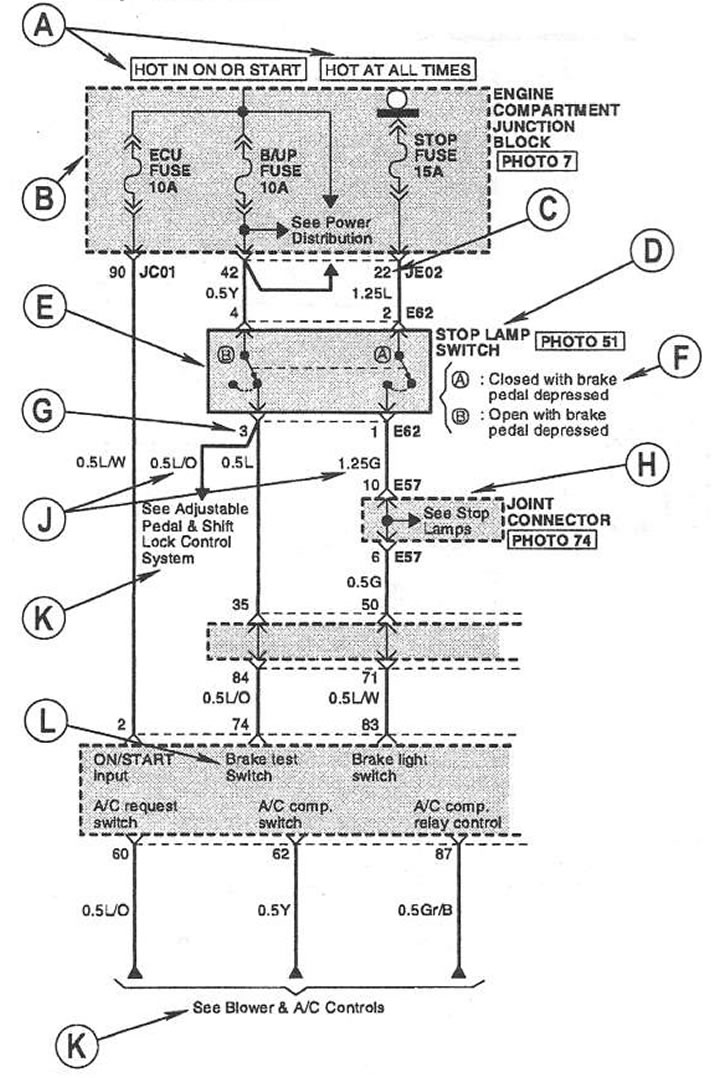
Symbols on the diagrams:
- A - The position of the key in the ignition lock is indicated, at which supply voltage is present in this circuit (HOT AT ALL TIMES - voltage is supplied constantly, regardless of the position of the key, HOT IN ON OR START - voltage is supplied when the ignition is turned on or when the engine is started);
- B - A dashed line indicates that this diagram shows a fragment of a block, device or element;
- C - The number of the contact in the switching unit in the engine compartment is indicated;
- D - The name of the block or element, and the number of the photo that shows the location of this element in the car.
- E - A solid line indicates a block, device or element;
- F - An additional condition for the operation of the element is indicated (in this case: contact "A" - open, and the contact "B"- closed when the brake pedal is not pressed;
- G - Designation of the connector number and pin numbers in the connector of this element;
- H - Symbol of the switching connector (Joint Connector);
- J - Designation of the section and color marking of the wire;
- K - An indication of the corresponding diagram or element of electrical equipment, which must be considered in conjunction with this given diagram;
- L - Designation of the input or output signal.
Connection designation with «weight» car
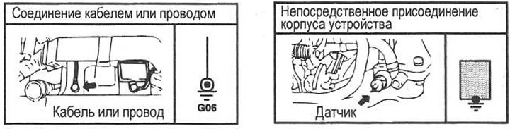
Harnesses and connectors
Classification and designation of harnesses:
- E - Engine compartment harnesses (Engine Room Harness & Engine Front Harness)
- C - Engine control harnesses (Control Hamess)
- M - Main harnesses in the cabin under the dashboard (Main Harness) and ceiling harnesses (Roof Harness)
- F - Floor harnesses (Floor Harness)
- A - Passive safety harnesses (Air Bag Hamess)
- D - Door harnesses (Door Harness)
- S - Heated and electrically adjustable front seat harnesses (Front Power Seat Harness)
- R - Harnesses for the rear of the car (Rear Hamess): luggage compartment harnesses (Trunk Room Harness) and trunk lid harnesses (Trunk Lid Hamess)
Classification and designation of connectors:
- Switching unit connectors (relay and fuse box). Designation: I / P - A - L.
- Wiring Harness Connectors (Harness Connector). Designation: two letters and two numbers (for example: EM 01 - connector connecting the engine compartment harness (E) and main harness (M) under the dashboard).
- Switching connectors (Joint Connector), are indicated on the diagrams by one letter and numbers (e.g. E57).
- Connectors located directly on blocks or components are also identified by a single letter and numbers (e.g. E62).
- If there are several connectors in the corresponding block, after the number (through the dash) indicate the number corresponding to the number of the connector in this block (e.g. C144-1).
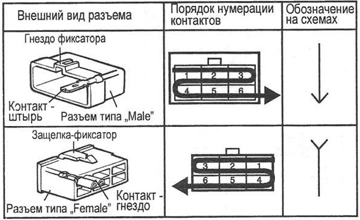
Type and designation of connectors, pin numbering order
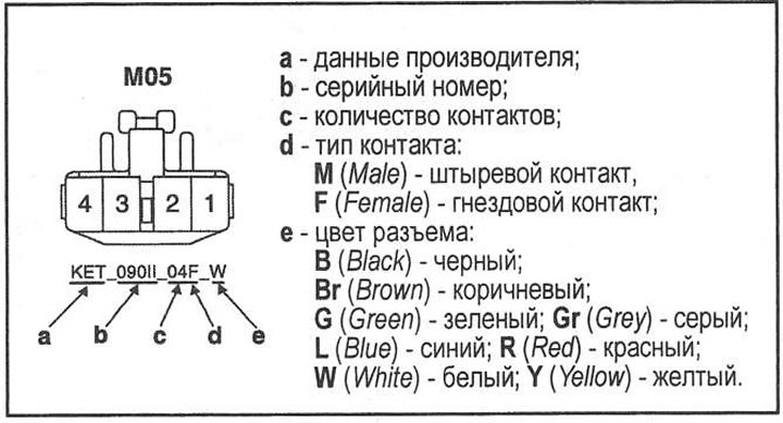
Connector markings
Wire marking
The diagrams show the marking of wires with alphanumeric characters.
For example: 1.25 G or 0.5 L/O.
The numbers indicate the cross section of the wire, in this example - 1.25 or 0.5 square meters. mm. Letter (or letters) indicate the color of the wire insulation. One letter - one-color wire, in this case - green; Two letters - two-color wire: the first letter is the main color of the insulation (blue), the second letter is the designation of the color of the strip (orange).
Wire color designation: B (Black) - black; Br (Brown) - brown; G (Green) - green; Gr (Grey) - grey; L (Blue) - blue; LG (Light Green) - light green; T (Tan) - yellow-brown; ABOUT (Orange) - orange: R (Pink) - pink; R (Red) - red: W (White) - white; Y (Yellow) - yellow; pp (Purple) - Dark red; LI (Light Blue) - blue.