
How to use wiring diagrams
Each diagram is an image of a separate subsystem of electrical equipment from a fuse (or floating rate) before "masses". For ease of understanding the circuit, the power supply is shown at the top of the diagram, and "weight" - in the lower part.
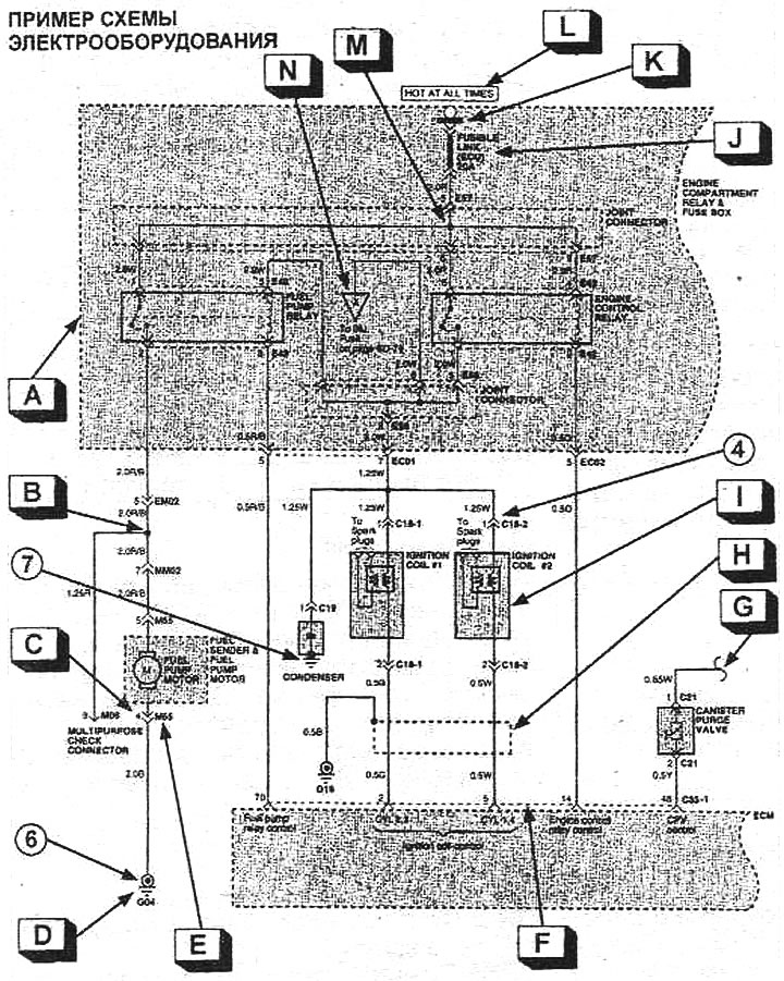
- A: In this case, the dashed line indicates that only part of the component is shown in the wiring diagram.
- B: Specifies the branch point of the wire where the diameter or color of the wire can change.
- C: Indicates the pin number in the connector.
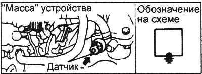
- D: Indicates the ground point. (The ground point number matches the number shown on the wiring harness and component location diagrams.)
- E: Indicates slot number only. It matches the connector number shown on the wiring harness diagram. The image of the connector is placed on a separate page.
- F: In case two or more connectors are connected to the same device, the dashed line (—) the pins of one connected connector are marked.
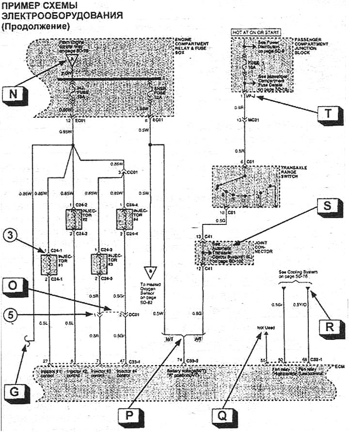
- G: Indicates that the circuit continues to the next part of the wiring diagram.
- H: Indicates shielded wiring harness connected to "weight".
- I: In this case, a solid line indicates that the component is shown in its entirety in the wiring diagram.
Note: about the component (e.g. a switch) the conditions of its functioning, characteristics, etc. can be given.
- J: Indicates the name of the fuse or fuse link and its rating.
- K: Indicates the presence of a jumper connecting this circuit to other fuses or fuse links.
- L: Indicates conditions (ignition key position), when the target is receiving power.
- M: Indicates a connection point for multiple wires within a connector.
- N: Indicates that the circuit continues at point Vb7 elsewhere in the diagram.
- A: Broken line (—) indicates that the pins refer to the same intermediate connector.
- R: Indicates the different equipment options for which the differences are shown in the wiring diagram.
- Q: Indicates that the pin is spare.
- R: Indicates that only part of the circuit is shown at this point on the wiring diagram and the entire circuit can be viewed at the link provided.
- S: The name of the target system that has a connection to the system in question.
- T: View Symbols "I/P-" in the connector number indicate that the connector is connected to the central junction point (relay box, fuse box, etc.).
Designations of connectors, connections and components
1: Designation of the connector on the wiring diagram.
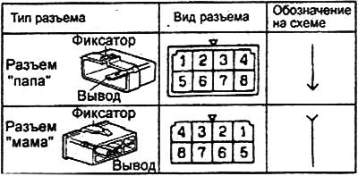
2: Connector pin numbering. The numbering of the connector pins is always indicated in the order shown by the arrow in the figure.
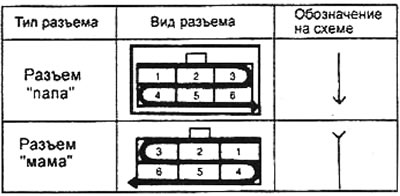
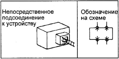
3: Indicates that the harness connector is connected directly to the device.
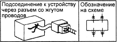
4: Indicates that the harness connector is connected to the device connector that includes the wiring.
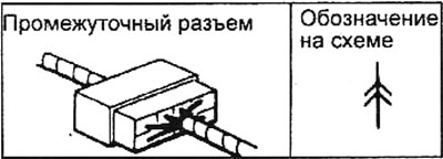
5: Indicates an intermediate connector.
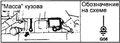
6: Indicates a connection to "weight" bodywork (metal body part).
7: Indicates a connection to "weight" devices (on the body of the device that is in contact with the body).
Connector markings
1. The connectors are divided into groups according to the location on the vehicle and have a symbolic designation (first character in designation).
| Group | Location |
| E | Engine compartment (engine wiring) |
| M | Salon, floor and roof (wiring of interior and exterior components) |
| WITH | Engine compartment (control wiring) |
| R | Rear body (trunk lid wiring) |
| I | Floor and front panel (wiring system SRS and instrument panel elements) |
| D | side doors (wiring inside the door) |
| G | Connection points with "weight" |
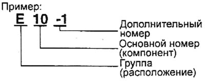
2. The designation of the standard connector of the component has a symbol of belonging to the group (by location), main part number (changes sequentially) and optional slot number (if the component has multiple connectors).
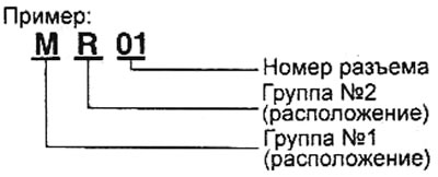
3. In the designation of the intermediate connector, which connects the wiring harnesses of different groups, there are symbols of belonging to groups (by location) for both wiring harnesses and connector number (changes sequentially).
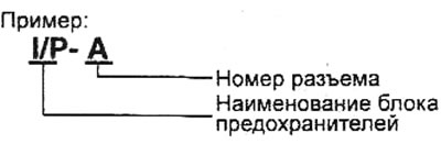
4. The designation of the fuse block connector contains symbols that uniquely characterize the location of the block on the car (for example, I / P - block in the cabin) and connector symbol (changes sequentially).
Wire marking
The wires differ in the color of the insulation and the section of the conductive part, depending on which electrical devices they are connected to.
The diagrams show the marking of the wire with a letter code (see picture):
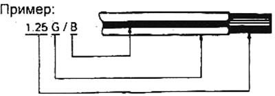
1.25: Wire size in mm2.
G: Primary wire color.
B: Optional wire color (stripe color), if the wire is bicolor.
Color coding
Colors of wire insulation, colors of fuses and fuses.
Note: with a two-letter wire insulation color code (e.g. R/G) the first letter indicates the main color of the wire (red), and the second - the color of the strip on the wire (green).
| Code | Color | Code | Color |
| IN | black | ABOUT | orange |
| BR | brown | R | pink |
| G | green | R | red |
| Gr | grey | W | white |
| L | blue | Y | yellow |
| LG | light green | pp | violet |
| T | yellow brown | LI | blue |
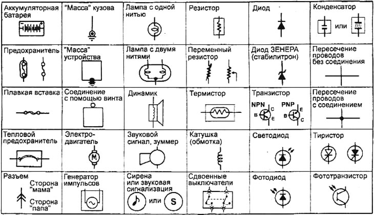
Table of symbols for electrical equipment components
Abbreviations
- ACC: When the ignition key is turned to the "ON" or "ACC" the power circuit starts to function.
- IG1: Even when the ignition key is turned to the "ST", the power circuit starts to function.
- IG2: When the ignition key is turned to "ST", the power circuit is not functioning.
- GND: "Weight".
- ILL: Illumination lamp.
- IND: Indicator (indication).
- DRL: Daytime outdoor lighting system.
- EPS: Electric Power Steering.