
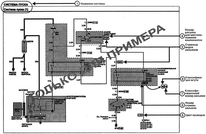
(1) System name:
- The diagram contains a description of electrical circuits with connectors, switches and wires related to a particular vehicle system, which makes it easier to find and fix a fault.
- It is very important to understand the possible location and possible cause of the malfunction before starting to diagnose a particular section of the circuit.
(2) Types of connectors:
This section provides the following information.
- Picture of the connector, front view (from the harness side, not from the part side).
- Connector color.
- Output number.
- Wire color.
- Purpose of the output.
Each pin on the connector is numbered according to point (3).
Type of connector and pin numbering order.
Terminals without connections are marked with a dash (-).
(3) Connector type and terminal numbering order:
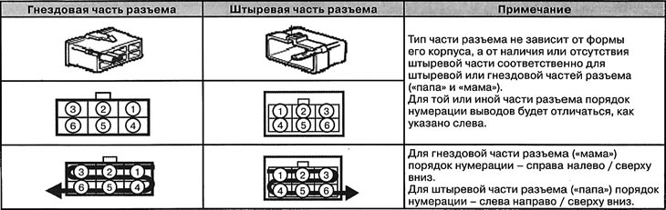
Note: In any other case, the view of all connectors is from the terminal side.
(4) Component location:
To make it easier to find a component, the number of the photo showing its location is given below the component designation. The photos themselves are located in the corresponding section of this chapter.
(5) Wire color designation:
| Designation | Wire color |
| IN | black |
| Vg | brown |
| G | green |
| Gr | grey |
| L | blue |
| Lg | light green |
| t | light brown |
| ABOUT | orange |
| r | pink |
| R | red |
| W | white |
| Y | yellow |
| Rr | purple |
| LI | light blue |
| X/Y | "X" color of the wire, "Y" color of the stripe on the wire |
Note: The wiring harness designation is also present on the harness itself in the vehicle.
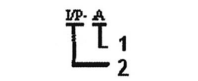
(7) Connector number:
The connector designation consists of a letter - the designation of the wire harness corresponding to its location, and the connector number. For example:
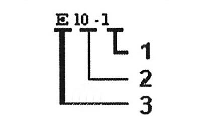
1. Number related to the auxiliary connector (serial number)
2. Number related to the main connector (serial number)
3. Letter indicating the location of the wiring harness (engine wiring harness)
Note: The connector used to connect different wire harnesses has the following designation.
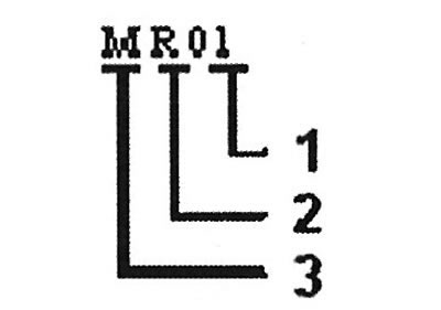
1. Number related to the main connector (serial number)
2. Rear Wiring Harness
3. Main wiring harness.
Distribution blocks also have their own designation, which consists of the designation of the wire harness corresponding to its location, and the connector number in the distribution block.
Note: The numbers in the wire designation indicate its diameter.
(6) Wire classification:
Wiring harnesses are classified based on their location in the vehicle.
| Symbol | Wiring harness name | Location |
| E | Front and Battery Wiring Harness | Engine bay, front bumper |
| M | Main Wiring Harness | Passenger cabin |
| F | Floor wiring harness | Floor |
| WITH | Electric heater control wiring harness | Engine compartment, passenger compartment |
| R | Wiring harness for tailgate, ceiling, rear parking sensors | Ceiling, tailgate, bumper |
| S | Seat Wiring Harnesses | Seats |
| D | Door Wiring Harnesses | Doors |
For example:
1. Connector designation.
2. Abbreviation for "Passenger Cabin Distribution Unit"
Note: In addition, the following abbreviations may be found on electrical diagrams:
- Automatic transmission - automatic transmission.
- MKPP - manual transmission.
- ECM - electronic engine control unit.
- ECM - electronic engine control unit.
- TCM - electronic transmission control unit.
- BCM - electronic control unit of the car body.
- SRS - additional passive safety system (SRS).
- ESP - Electric Power Steering.
- EMS - engine management system.
- ABS - anti-lock braking system.