
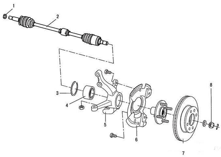
Front wheel drive: 1 – retaining ring; 2 – wheel drive shaft; 3 – retaining ring; 4 – hub bearing; 5 – steering knuckle; 6 – protective cover; 7 – brake disc; 8 – nut for fastening the drive in the front wheel hub.
The drive of each wheel consists of two constant velocity joints and a shaft. The outer joint consists of a housing, a separator, an inner race and six balls. Grooves for placing the balls are made in the joint housing and in the race. The grooves in the longitudinal plane are made along the radius, which ensures the required angle of rotation of the outer joint.
The splined end of the joint housing is installed in the hub of the front wheel and secured to it with a nut. The joint cage is installed on the splines of the shaft between the spring washer, thrust ring and retaining ring.
Note: To prevent the 09568-34000 puller from falling, hang it with a wire or rope from a nearby component.
The inner joint differs from the outer joint in that the housing and cage tracks are straight, which allows the joint parts to move in the longitudinal direction (this is necessary to compensate for movements caused by vibrations of the front suspension and power unit), and also in that the elements transmitting engine torque are not balls, but rollers.
Balls of one sorting group are installed in the outer hinge; if necessary, all six hinge balls are replaced; the balls must be of the same sorting group.
The hinge parts are lubricated with a special grease for constant velocity hinges, which is placed in the hinge housings during assembly. The hinges are sealed with rubber protective covers, which are secured with metal clamps.