
Contents: Technical data ⇓ Adjustment data ⇓ Recommended lubricants ⇓ Tightening torques, Nm ⇓ General information ⇓
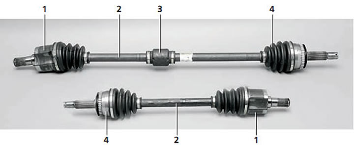
Right (top) and left wheel drives: 1 - internal hinge; 2 - shaft; 3 - dynamic damper; 4 - outer hinge.
Technical data
| Name/Engine | 1.1 l | 1.3, 1.5, 1.6 l |
| Outer joint of the drive shaft | B.J. | B.J. |
| Inner joint of the drive shaft | T.J. | T.J. |
| Maximum allowable rotation angle of the BJ joint. | More than 45.3° | More than 45° |
| Maximum allowable rotation angle of the TJ joint. | More than 22.3° | More than 22.5° |
BJ: Bitfield hinge
TJ: tripoid joint
Adjustment data
| Maximum permissible axial clearance of the front wheel hub, mm | 0,008 |
| Maximum permissible starting torque of the front wheel bearing, N | 0,99 |
| Maximum permissible starting torque of the rear wheel bearing, N | 1,8 |
Recommended lubricants
| Name | Recommended lubricants | Quantity |
| BJ joint drive shaft (1.1L manual transmission) | CENTOPLEX278M/136K | 70+6 g |
| Joint T. J. drive shaft (1.1L manual transmission) | KLKT.J. 41–182 | 95±6g |
| Joint B. J. of the drive shaft (1.3, 1.5, 1.6 hp MKL/AKP) | CENTOPLEX 278M/136K | 85±6 g |
| TJ joint of the drive shaft (1.3, 1.5, 1.6 l with manual/automatic transmission) | KLKT.J. 41–182 | 95+6 g |
Tightening torques, Nm
| Wheel mounting nuts | 90–110 |
| Drive shaft mounting nuts | 200–260 |
| Steering knuckle to strut mounting nut | 130–150 |
| Lower arm ball joint to steering knuckle mounting nut | 60–72 |
| Tie rod end to steering knuckle | 24–34 |
| Caliper to steering knuckle | 65–75 |
| Rear wheel hub mounting nut | 80–90 |
| Lower rear shock mount | 100–120 |
Attention!
- New self-locking nuts must be used during installation.
- After removing the fasteners, they must be installed in the same places and in the same position. If a fastener needs to be replaced, the original fastener or one of the same size and characteristics must be used.
- Tightening of fasteners must be carried out only with the recommended tightening torques.
General information
The drive shafts transmit torque from the engine, gearbox and differential to the front wheels. In the gearbox housing, the drive shafts are secured with splined connections to the differential axle gears. The splined end of the inner joint of the drive shaft is fixed in the axle gear by a spring retaining ring. During installation, the retaining ring is compressed, entering the shaft groove. After the shaft is completely installed in the differential axle gear, the retaining ring is released and fixes the splined end from axial movement. The outer joints of the drive shafts are attached to the hubs of the front wheels, mounted on bearings. The shaft is fastened to the hub by a nut with a flange. To prevent the nut from loosening, the flange of the nut is bent into the recess of the drive shaft.
(The material was obtained from a web resource: «www.hyundaibook.ru»)
Constant velocity joints (CV joints) are installed on both sides of the drive shaft. All outer CV joints are Birfield type, and the inner ones are tripod type. Tripod type CV joints are used to prevent engine vibrations from being transmitted through the drive shafts to the car body. CV joints are necessary for transmitting torque and compensating for front suspension movement. CV joints also allow the length of the drive shaft to be changed and torque to be transmitted at constantly changing angles.