
Contents: Bleeding the Clutch Hydraulic Drive ⇓ Clutch master cylinder ⇓ Clutch pedal ⇓ Clutch housing and driven disc ⇓ Clutch slave cylinder ⇓ Useful information and tips ⇓
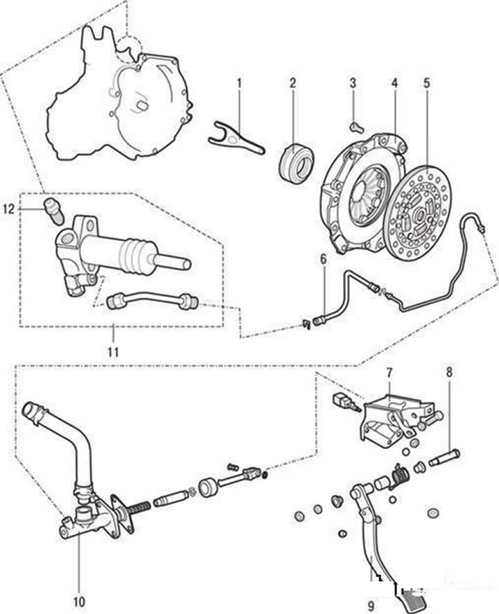
Clutch and its drive: 1 – clutch release fork; 2 – clutch release bearing; 3 – clutch housing mounting bolt; 4 – clutch housing; 5 – driven clutch disc; 6 – clutch drive pipeline; 7 – clutch pedal bracket; 8 – clutch pedal axle; 9 – clutch pedal; 10 – clutch master cylinder; 11 – clutch slave cylinder; 12 – clutch slave cylinder bleed nipple
Bleeding the Clutch Hydraulic Drive
The clutch hydraulic system should be bled every time the connecting pipe, hose and/or master cylinder is removed, and also when the clutch pedal becomes "soft".
Caution! Use only the specified brand of working fluid. Do not mix fluids of different brands. Use DOT-3 or DOT-4 fluid.
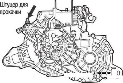
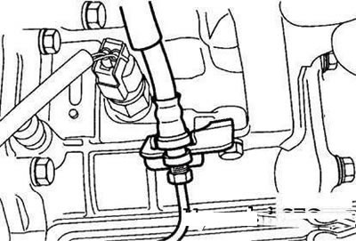
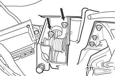
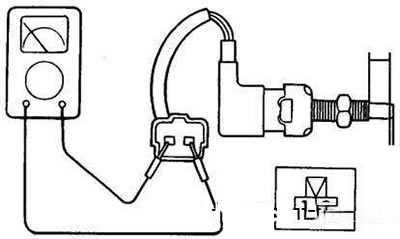
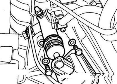
Location of the clutch hydraulic bleed nipple
Loosen the bleed screw on the slave cylinder.
Slowly press the clutch pedal all the way until the fluid stops leaking.
While holding the pedal down, tighten the bleed screw.
Add the required grade of fluid to the reservoir to the normal level.
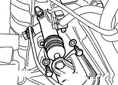
Clutch master cylinder
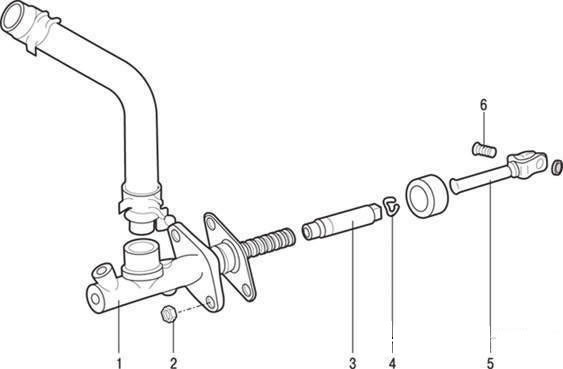
Clutch master cylinder: 1 – clutch master cylinder housing; 2 – clutch master cylinder fastening nut; 3 – piston; 4 – retaining ring; 5 – pusher with damper; 6 – pusher axis
Removal
Drain the working fluid through the bleed nipple.
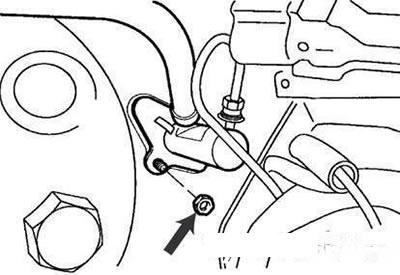
Clutch master cylinder mounting nut
Loosen the master cylinder mounting nut.
Disconnect the clutch hydraulic lines and hoses.
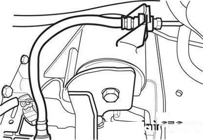
Pipeline fastening clamp to gearbox
Remove the clamp securing the pipeline to the gearbox.
Check the hose and line for corrosion, pitting and scoring.
Installation
Connect the pipe to the working cylinder.
Flexible clutch hydraulic hose
Attach the flexible hose and secure it with a clamp.
Install the master cylinder.
Attach the push rod to the clutch pedal.
Bleed the clutch hydraulic system.
Disassembly
Remove the piston retaining ring.
Remove the push rod assembly with the piston, being careful not to damage the cylinder body and piston.
Checking the technical condition
Check the cylinder bore for corrosion, pitting and scoring.
Check the cylinder seal for wear or distortion.
Check the piston for corrosion, pitting or scoring.
Check the cleanliness of the pipeline.
Check the cylinder bore with a bore gauge and the piston outer diameter with a micrometer.
If the clearance between the piston and the cylinder exceeds the maximum permissible size (0.15 mm), replace the master cylinder or piston.
Assembly
Apply DOT-3 or DOT-4 working fluid to the cylinder bore and the outer surface of the piston.
Insert the piston into the cylinder.
Install the piston retaining ring.
Install the pusher.
Attach the hose to the cylinder body.
Clutch pedal
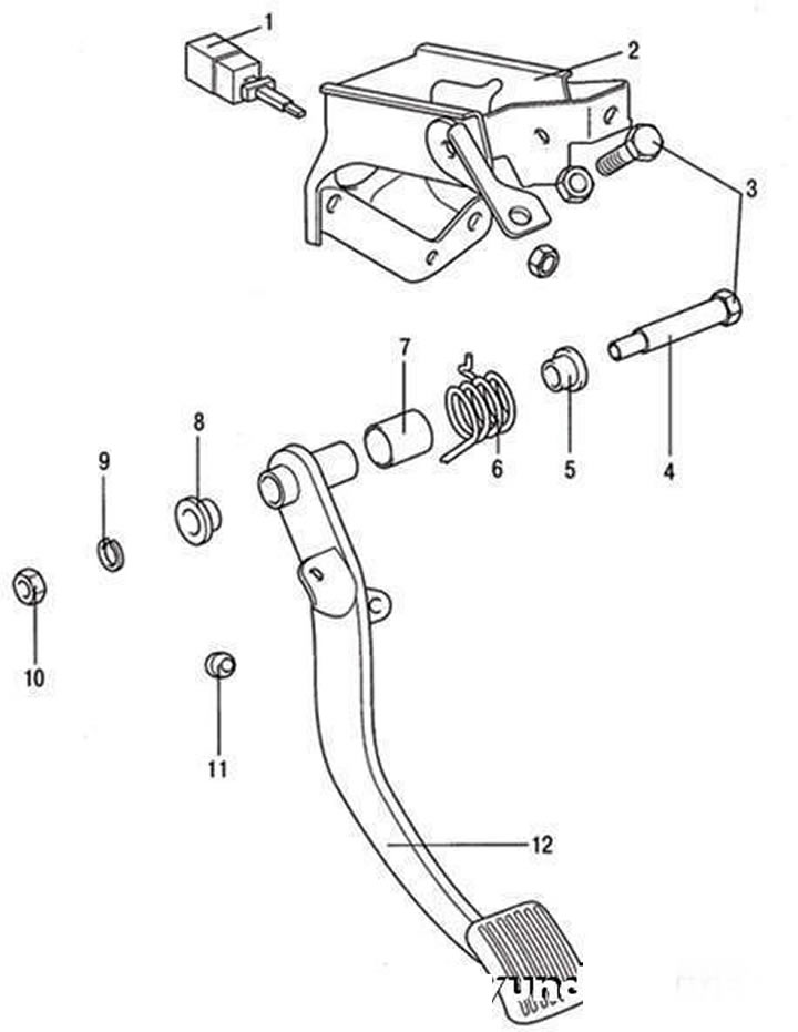
Clutch pedal and its mounting bracket: 1 – ignition lock switch; 2 – pedal bracket; 3 – pedal bracket mounting bolt; 4 – pedal axle; 5 – inner pedal bushing; 6 – return spring; 7 – outer pedal bushing; 8 – inner pedal bushing; 9 – spring washer; 10 – pedal axle nut; 11 – pedal stop; 12 – clutch pedal
Removal
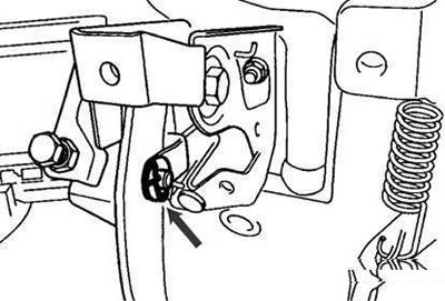
Clutch pedal pusher axle cotter pin
Remove the cotter pin and washer.
Clutch pedal mounting nuts
Loosen the pedal mounting bolts.
Checking the technical condition
Check the following:
- pedal axle and bushing for wear;
- clutch pedal for bending and tilting;
- return spring for damage or weakening;
- pedal pad for damage or wear;
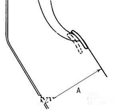
Measuring the height of the clutch pedal above the floor
- the height of the pedal above the floor A (from the outer surface of the pedal pad to the floor) (Figure 3.10). It should be 160.7 mm.
If the pedal height above the floor is not correct, adjust it as follows.
Caution: When adjusting the pedal height, make sure that the push rod does not move towards the master cylinder.
1. Use the bolt to adjust the pedal height, then tighten the lock nut.
Caution: After adjustment, tighten the bolt until it touches the pedal stop, then tighten the lock nut.
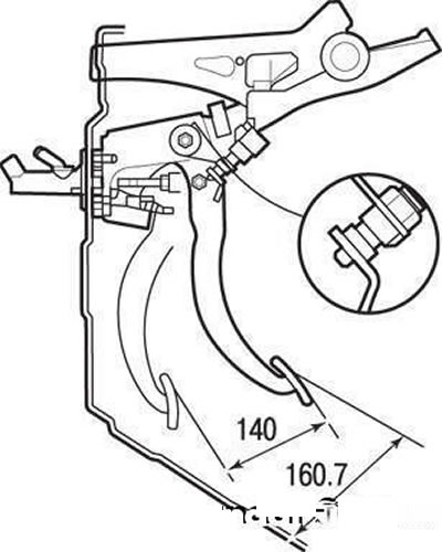
Height above floor and clutch pedal travel
2. Rotate the pusher to adjust its length to the new pedal height, then secure the pusher with the nut.
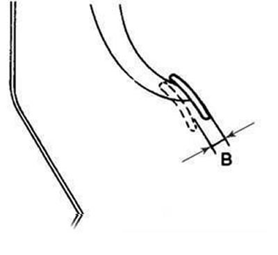
Free play of the clutch pedal
After completing the adjustment, make sure that the clutch pedal free play (measured from the surface of the pedal pad) is within 6–13 mm.
If the free travel of the clutch pedal is not normal, then air has entered the hydraulic drive or the master cylinder is faulty. Bleed the hydraulic drive and check the master cylinder or clutch.
Circuit diagram for checking the integrity of the electrical circuit between the switch contacts
Checking the ignition interlock switch. Check the integrity of the electrical circuit between the switch contacts.
Installation
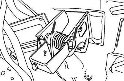
Places to apply universal grease
Apply general purpose grease to areas indicated by arrows.
Tighten the nuts.
Install the clutch pedal axle cotter pin.
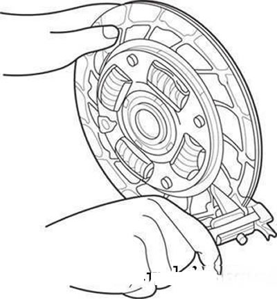
Clutch housing and driven disc
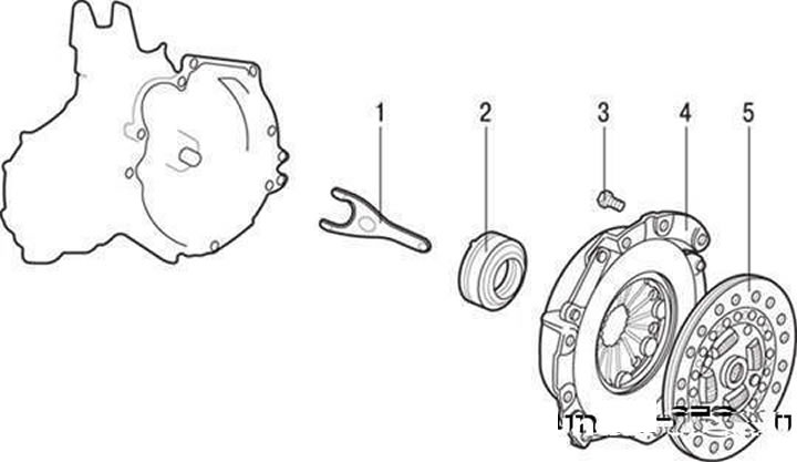
Clutch housing and driven disc: 1 – clutch release fork; 2 – clutch release bearing; 3 – clutch housing mounting bolt; 4 – clutch housing; 5 – driven clutch disc
Removal
Drain the fluid from the clutch hydraulic drive and the oil from the gearbox housing.
Remove the gearbox (see subsection "Gearbox").
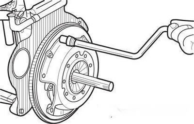
Insert drift 09411-25000 into the driven disk hub hole to prevent it from falling.
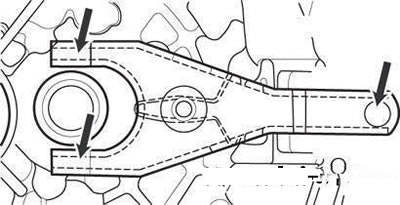
Loosen the crosswise tightening of the clutch housing to flywheel mounting bolts.
Loosening the bolts securing the clutch housing to the flywheel
Loosen the bolts one by one, one or two turns each time, to prevent the casing flange from warping.
Caution: Do not use solvents to clean the driven disc and clutch release bearing.
Technical condition check
Clutch housing. Check the ends of the diaphragm spring petals for wear and height differences.
Check the surface of the pressure plate for wear, cracks and discoloration.
Check for loose rivets and replace the clutch cover if necessary.
Driven disc. Check the friction linings for loose rivets, signs of uneven contact, damage from seizure, and oil or grease buildup. Replace the damaged driven disc if necessary.
Checking the thickness of the driven disk in a free (unloaded) state
Check the thickness of the driven disk in a free state.
Check the disc springs for play and damage, replace the faulty disc if necessary.
Clean the splines of the gearbox input shaft and install the driven disk.
If the disc moves with difficulty along the shaft splines or if there is excessive clearance, replace the driven disc and/or the input shaft of the gearbox.
Caution! The clutch release bearing contains grease. Do not use solvents to clean the bearing.
Clutch release bearing. Check the clutch release bearing for binding, damage, or excessive noise. Check the contact points of the diaphragm spring with the bearing race for wear.
Replace the bearing if the contact points with the clutch release fork are severely worn.
Clutch release fork. Replace the clutch release fork if it is heavily worn where it contacts the clutch release bearing.
Installation
Apply multi-purpose grease to the clutch release fork where it contacts the release bearing and slave cylinder.
Place where to apply universal grease on the clutch release fork
Apply lubricant.
Apply general purpose grease to the clutch release bearing groove.
Recommended lubricant: CASMOLY L9508.
Apply CASMOLY L9508 universal grease to the clutch release fork where it contacts the clutch release lever axle.
Clean the flywheel and pressure plate surfaces thoroughly with fine-grit sandpaper and ensure that there are no traces of oil or grease on them.
Apply a small amount of CASMOLY L9508 universal grease to the splines of the driven disk hub and the gearbox input shaft.
Clutch slave cylinder mounting bolts
Caution: When installing the clutch, do not apply too much grease to the indicated areas, as this may cause slippage and jerking during clutch operation.
Using tool 09411-25000, install the driven disk onto the flywheel with the side with the factory marking facing the pressure plate.
Install the clutch housing onto the flywheel and screw in the six mounting bolts.
Tighten the bolts crosswise to 15–22 N·m. Tighten the bolts alternately, one or two turns at a time, to prevent warping of the clutch housing flange.
Remove the driven disk centering mandrel.
Install the gearbox (see subsection "Gearbox").
Adjust the clutch pedal free play.
Caution! Apply only the required amount of grease. Excess grease may cause slippage and jerking during clutch operation.
Clutch slave cylinder
Removal
Disconnect the connecting pipe from the working cylinder.
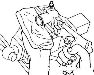
Removing the piston from the cylinder
Loosen the working cylinder mounting bolt.
Checking the technical condition
Check the slave cylinder for signs of fluid leakage.
Check the slave cylinder boot for damage.
Disassembly
Disconnect the connecting hose from the cylinder, remove the valve plate, spring, pusher and boot.
Carefully remove dirt from around the piston bore of the working cylinder.
Remove the piston from the cylinder by blasting compressed air into the cylinder.
Caution! Cover the working cylinder with a rag beforehand, as the piston may fly out at high speed and cause injury.
Increase the air pressure gradually to prevent brake fluid from escaping and coming into contact with your eyes or skin.
Checking the technical condition
Check the working cylinder mirror for corrosion or damage.
Using a bore gauge, check the inner diameter of the cylinder in three places (lower, middle and upper parts). If the clearance between the piston and the cylinder exceeds the maximum permissible value, replace the working cylinder.
The maximum permissible clearance between the piston and the cylinder is 0.15 mm.
Assembly
Apply the required grade of brake fluid to the inner surface of the working cylinder and the outer surface of the piston and piston seal and install the piston into the cylinder.
Fluid used: DOT-3 or DOT-4 brake fluid.
Installation
Install the valve plate, tappet and boot.
Apply CASMOLY L9508 grease to the push rod axle.
Install the clutch slave cylinder and connect the pipeline to it.
Clutch slave cylinder mounting bolts
Screw in the slave cylinder mounting bolts.
Useful information and tips
Reasons for clutch slippage or incomplete disengagement when pressing the pedal
Clutch slippage is manifested in the fact that, with a perfectly serviceable engine, the car does not climb well and accelerates slowly. This can be caused by oiling or severe wear of the disks, decreased elasticity of the springs, or lack of free travel of the clutch pedal.
Incomplete disengagement of the clutch causes difficulty and noise when changing gears and can lead to premature failure of synchronizers and accelerated wear of the gearbox teeth. This malfunction most often occurs when the disks are dirty, skewed or deformed, the position of the release levers is incorrectly adjusted, or the free travel of the clutch pedal is too large.
It should be borne in mind that noise in the gearbox is not always a consequence of incomplete disengagement of the clutch. Noise can occur due to wear or improper adjustment of bearings, wear or improper engagement of bevel gears. A loud knock in the indicated places indicates a serious malfunction that requires immediate stopping of the car and repair of the unit.
Reasons for difficult gear shifting or spontaneous gear shifting
Difficulty shifting gears or their spontaneous disengagement is the result of wear of locks and clamps or the gear shift mechanism drive. Here, you cannot do without serious repairs.
Such malfunctions can be prevented in the following ways: periodically carefully check the reliability of the fastening of all units and parts of the power transmission, monitor the oil level in the gearbox and change it in a timely manner.