Contents: Tightening torques for threaded…⇓ Technical specifications ⇓ Data for checks and adjustments ⇓ Lubricants used ⇓ General information ⇓
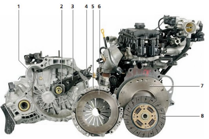
Clutch elements: 1 - clutch housing; 2 - clutch release bearing; 3 - clutch release fork; 4 - clutch hydraulic drive slave cylinder; 5 - clutch housing; 6 - pressure plate; 7 - flywheel; 8 - driven disk with spring damper of torsional vibrations
Tightening torques for threaded connections, Nm
| Pedal to bracket mounting bolt | 25–35 |
| Master cylinder to pedal bracket mounting bolt | 17–26 |
| Union nut for pipeline fastening | 13–17 |
| Pipeline holder | 4–6 |
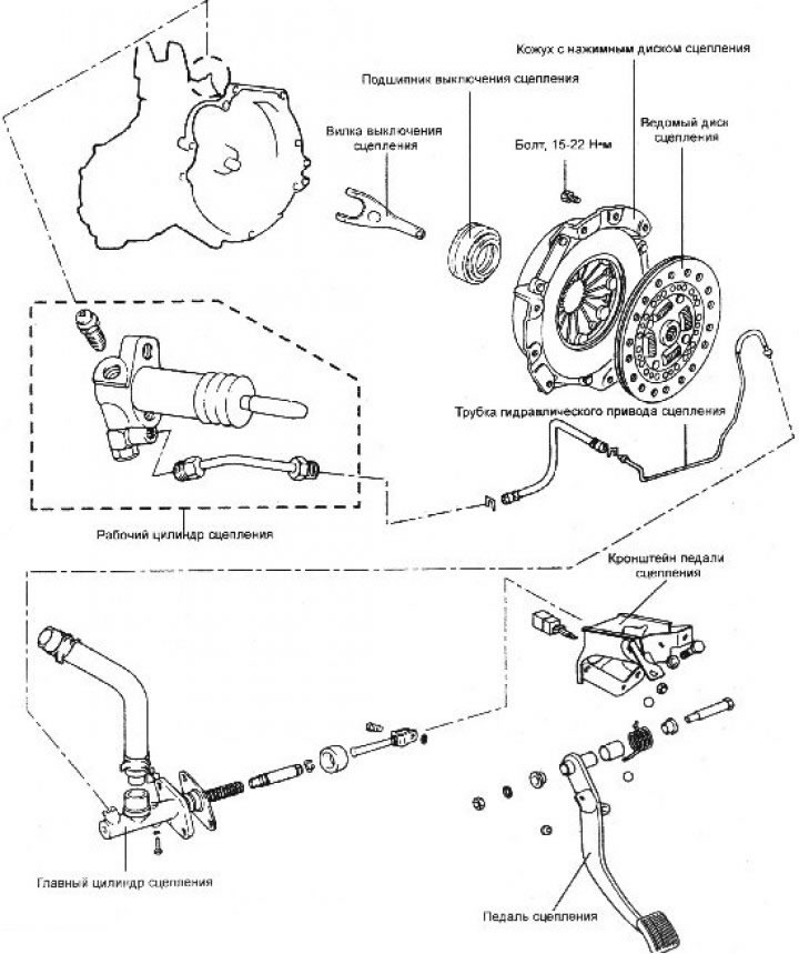
| Working cylinder mounting bolt | 15–22 |
| Hollow bolt for fastening the pipeline to the working cylinder | 25 |
| Clutch housing mounting bolts | 15–22 |
| Nut securing master cylinder pushrod to pedal | 9–14 |
| Ignition interlock switch mounting nut | 8–10 |
Technical specifications
| Clutch drive type | Hydraulic |
| Clutch slave disc | Dry, diaphragmatic |
| External/internal diameter of driven disk, mm | 215/145 |
| Clutch housing assembly with pressure plate | With diaphragm pressure spring |
| Inner diameter: working cylinder, mm master cylinder, mm | 20,64 15,57 |
Data for checks and adjustments
| Clutch drive type | Hydraulic |
| Thickness of the driven disk (in free state) mm: engines 1.3; 1.5 and 1.6 l 1.1L engine | 8,5±0,3 8,0±0,3 |
| Free travel of clutch pedal, mm | 6-13 |
| Clutch pedal height above floor, mm | 160,7 |
| Clutch pedal travel, mm | 140 |
| Clearance between working cylinder and piston, mm | 0,15 |
| Clearance between master cylinder and piston, mm | 0,15 |
Lubricants used
| Place of application | Name |
| Contact surface of the fork with the clutch release bearing | CASMOLY L9508 |
| Inner surface of clutch release bearing | CASMOLY L9508 |
| Working cylinder mirror, piston outer surface and cuff | DOT-3 brake fluid or DOT-4 |
| Clutch driven disc splines | CASMOLY L9508 |
| Master cylinder mirror and piston outer surface | DOT-3 brake fluid or DOT-4 |
| Master cylinder push rod, push rod shaft and washer | Wheel Bearing Grease SAE J310a, NLGI No.2 |
| Clutch pedal axle and bushings | SAE J310a, Chassis Grease, NLGI-No.1 |
| The contact surface of the clutch release fork with the push rod of the working cylinder | CASMOLY L9508 |
General information
The clutch is located between the engine and the gearbox and is designed to disconnect and connect the flywheel located on the engine crankshaft and the input shaft of the gearbox.
The clutch consists of a driven (friction) disk, a clutch housing with a pressure disk and a diaphragm spring, and a clutch release mechanism. The friction disk consists of two annular friction linings, which are fixed to the hub through damper springs.
The diaphragm spring mechanism creates a force that combines the work of the flywheel, pressure plate and slave disk to ensure joint rotation, in which case the clutch is engaged and transmits torque from the engine to the gearbox. The clutch is controlled by the clutch pedal.
The clutch is released as follows. Pressing the clutch pedal moves the piston in the master cylinder, compressing the fluid, the pressure of which is transmitted through the hose to the slave cylinder of the clutch, the piston of which, in turn, acts on the clutch release fork. The clutch release fork moves the clutch release bearing, which presses on the center of the diaphragm spring, thus releasing the engagement force along the perimeter of the spring and moves the pressure plate back. This releases the slave disk, after which the engine shaft and the gearbox shaft can rotate independently of each other.
Friction linings are fixed on both sides of the driven disk. The leading part of the disk is connected to the hub through the parts of the torsional vibration damper, which provides an elastic connection between them. The vibration damper reduces dynamic loads that cause twisting (untwisting) of the transmission shafts, which occur when the vehicle speed changes abruptly, when driving over uneven roads, when the clutch is abruptly engaged, and also due to uneven engine torque. Elastic vibrations of transmission parts lead to noise in mechanisms and units, as well as vibrations, which may result in damage to the parts if the amplitude of elastic vibrations reaches significant values. The damper serves to absorb the energy of elastic torsional vibrations.