Contents: Adjusting the clearance between the…⇓ Checking the pull-in winding of the…⇓ Checking the holding winding of the…⇓ Idle mode check ⇓ Checking the release of the traction…⇓ Removal and installation ⇓ Checking the collector ⇓ Checking the freewheel clutch ⇓ Cleaning starter parts ⇓ Replacing brushes ⇓
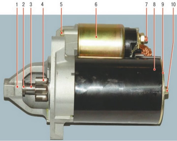
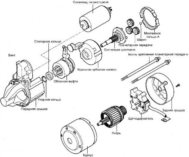
Starter: 1 - front cover; 2 - limiting ring; 3 - anchor; 4 - drive gear; 5 - traction relay mounting screw; 6 - electromagnetic traction relay; 7 - contact bolt; 8 - body; 9 - back cover; 10 - rear cover mounting bolt
The electric engine starting system consists of a battery, a starter, a traction relay, an ignition switch, a starter interlock switch (only on vehicles with automatic transmission), connecting wires and battery wires.
When the ignition key is turned to the engine start position, the battery current is supplied to the winding of the starter traction relay. This causes the traction relay anchor and the freewheel clutch drive lever to shift, and the drive pinion engages with the flywheel ring gear. The contacts close and the starter electric motor is turned on.
The presence of a freewheel clutch prevents the armature winding and collector from becoming dislodged.
Adjusting the clearance between the end of the drive gear and the stop
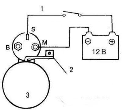
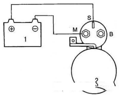
Wiring diagram for the battery when adjusting the gap between the end of the drive gear and the stop: 1 – switch; 2 – excitation winding wire; 3 – starter
The diagram for connecting the battery when adjusting the gap between the end of the drive gear and the stop is shown in the figure.
Disconnect the excitation winding wire from the "M" terminal of the traction relay.
Connect a 12-volt battery to the "S" and "M" terminals.
The drive gear should move into the engaged position.
Attention! To prevent the winding from burning out, carry out the test as quickly as possible (within no more than 10 s).
Using a feeler gauge, check the clearance between the end of the drive gear and the stop.
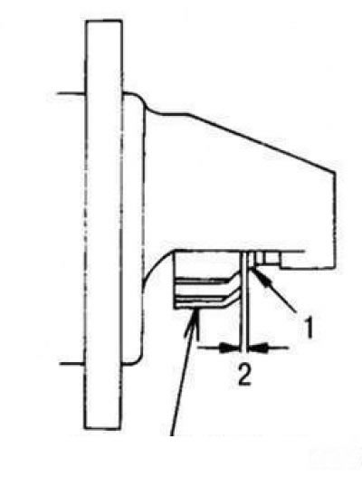
Clearance between the end of the drive gear and the stop: 1 – stop; 2 – gap between the end of the drive gear and the stop; 3 – drive gear
The gap between the end of the drive gear and the stop should be 0.5–2.0 mm.
If the axial play of the armature shaft is not within the specified limits, adjust it by installing or removing adjusting shims between the traction relay and the cover on the drive side.
Checking the pull-in winding of the traction relay
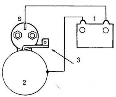
Wiring diagram of the storage battery when checking the starter traction relay pull-in winding: 1 – Battery; 2 – starter
The connection diagram of the storage battery when checking the starter traction relay pull-in winding is shown in the figure.
Disconnect the excitation winding wire from the "M" terminal of the traction relay.
Connect a 12-volt battery to the "S" and "M" terminals.
Attention! To prevent the winding from burning out, perform the test as quickly as possible (within no more than 10 s).
If the drive gear shifts to the engagement position, the relay pull-in coil is OK. If this does not happen, replace the traction relay.
Checking the holding winding of the traction relay
Wiring diagram of the storage battery when checking the holding winding of the starter traction relay: 1 - Battery; 2 – starter; 3 – excitation winding wire
The diagram for connecting the storage battery when checking the holding winding of the starter traction relay is shown in the figure.
Disconnect the excitation winding wire from the "M" terminal of the traction relay.
Connect a 12-volt battery to the "S" terminal and ground.
Attention! To prevent the winding from burning out, carry out the test as quickly as possible (within no more than 10 s).
If the drive pinion extends to the engagement position, the relay is OK. If the pinion extends and returns to its original position multiple times, there is a break in the holding winding. Replace the traction relay.
Idle mode check
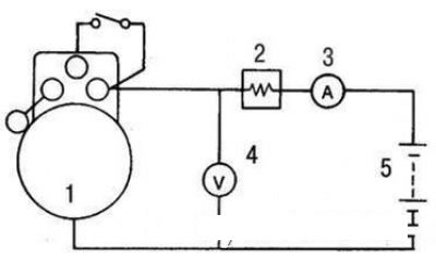
Battery connection diagram when checking the starter in idle mode: 1 – starter; 2 – carbon rheostat; 3 – ammeter; 4 – voltmeter; 5 – Battery
Clamp the starter in a vice with soft jaws and connect a fully charged 12-volt battery to the starter as shown.
Connect a control ammeter (with a 100 A scale) and a carbon rheostat.
Connect a voltmeter (with a 15V scale) in parallel with the starter.
Set the carbon rheostat to the off position.
Connect the wire from the negative terminal of the battery to the starter housing.
Using a rheostat, set the voltage to 11 V on the voltmeter.
Turn on the starter and check that the maximum current consumption is within the norm, as well as the smoothness and ease of rotation of the starter armature.
The current consumption must not exceed 90 A, and the rotation speed of the anchor must not be less than 2800 min⁻¹.
Checking the release of the traction relay

Wiring diagram of the storage battery when checking the release of the starter traction relay: 1 - Battery; 2 – starter; 3 – excitation winding wire
Disconnect the excitation winding wire from the "M" terminal of the traction relay.
Connect a 12-volt battery to the "M" terminal and ground.
Attention! To prevent the winding from burning out, carry out the test as quickly as possible (within no more than 10 s).
Pull the drive pinion out and in. If the pinion quickly returns to its original position, the traction relay is OK. Otherwise, replace the traction relay.
Removal and installation
1. Disconnect the cable from the negative terminal of the battery.
2. Disconnect the speedometer drive cable and gear shift cable.
3. Disconnect the connector from the starter and the wire from the terminal.
4. Unscrew the bolts and remove the starter.
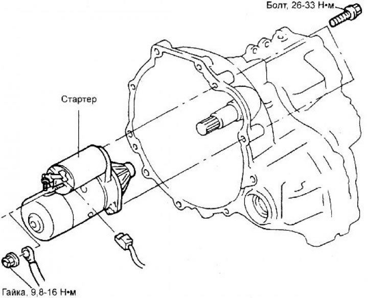
5. Installation is carried out in the reverse order of removal.
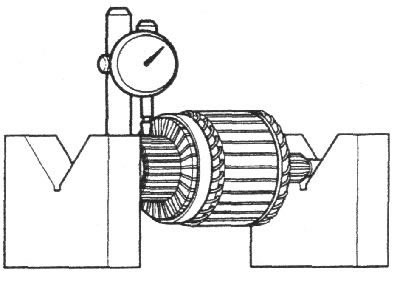
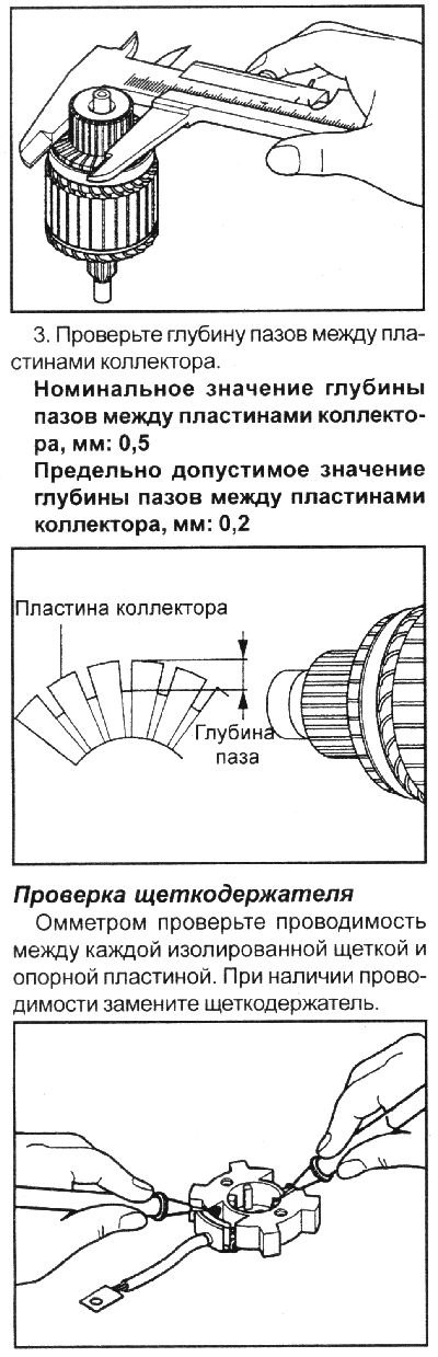
Checking the collector
1. Install the anchor in two V-shaped prisms and use an indicator to check the collector runout.
- Nominal value of collector runout, mm: 0.05
- Maximum permissible value of collector runout, mm: 0.1
2. Measure the diameter of the manifold.
- Nominal value of manifold diameter, mm: 29.4
- Maximum permissible value of collector diameter, mm: 28.4
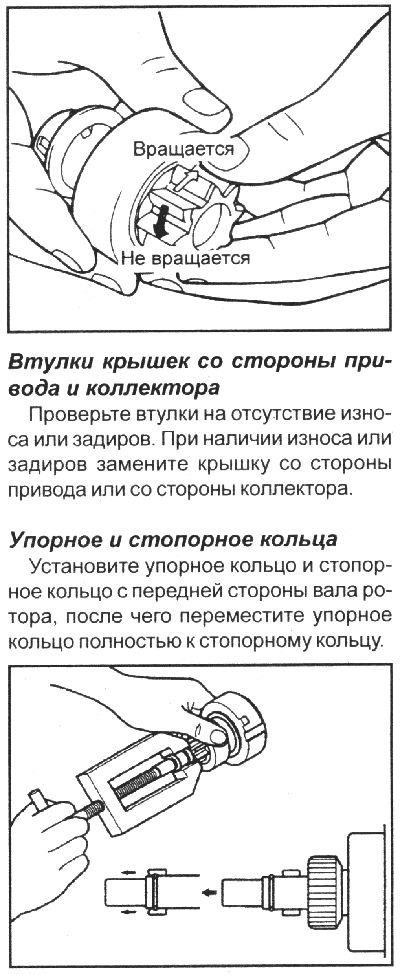
Checking the freewheel clutch
1. Hold the freewheel housing with your hand and turn the pinion. The pinion should turn freely clockwise and lock when turned counterclockwise.
2. Check the condition of the freewheel clutch gear teeth and replace them if damaged. Also check the condition of the flywheel ring gear teeth.
Cleaning starter parts
1. Do not wash parts by immersing them in solvent, as this will damage the stator winding, traction relay and/or armature. Clean parts only by wiping with a dry, clean cloth.
2. Do not immerse the gear with the freewheel clutch in solvent, as this will wash out the grease embedded in the freewheel clutch during the manufacturing process.
3. Clean the drive with a brush soaked in cleaning solvent, then wipe with a dry, clean cloth.
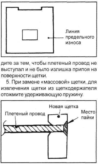
Replacing brushes
1. Replace worn or oily brushes.
2. When replacing the excitation winding brush, use pliers to break off the worn brush, being careful not to damage the braided wire.
3. Use sandpaper to smooth the end of the braided lead to ensure good contact with the new brush.
4. Insert the braided wire into the hole of the new brush and solder it