
Contents: Safety precautions when working with…⇓ Elements of the ignition system ⇓ Ignition coil ⇓ Spark plugs ⇓
The ignition system produces a spark in each cylinder at a certain point in time. It ignites the supplied fuel-air mixture. To do this, the ignition coil converts the 12 V battery voltage into 25,000–30,000 V. The electronic control unit of the engine management system is equipped with a memory for recording fault codes that occur in the ignition system while the car is moving. Before repairing the ignition system, it is necessary to first read the fault codes from the control unit memory. The control unit memory is interrogated using a special device through the diagnostic connector located under the instrument panel.
Safety precautions when working with electronic ignition system components
The voltage in the high-voltage part of the ignition system is up to 30 kV. Under unfavorable circumstances, such as high humidity in the engine compartment, voltage surges can break through the insulation, which can cause electric shock when touched. To avoid injury and/or damage to the electronic ignition system, when working on cars with electronic ignition, the following rules must be followed:
- before turning the crankshaft with the starter (for example, when checking the compression), turn off the ignition and disconnect the contact connector from the power amplifier located on the ignition coil;
- do not touch or disconnect high-voltage ignition system wires with your hands while the engine is running or when the engine crankshaft is being turned by the starter;
- disconnect ignition system wires only when ignition is off;
- connect and disconnect control devices (tachometer and ignition tester) only when the ignition is off;
- when towing a vehicle that has a fault or is suspected of having a fault in the ignition system, disconnect the wire from the power amplifier;
- it is permissible to start the engine within 1 min using a quick charger with a maximum voltage of 16.5 V. After each start attempt, a pause of at least 1 min should be made;
- the ignition coil cannot be replaced with a coil from another model or modification of the car with a different engine. Under no circumstances should an ignition coil from a contact ignition system be installed;
- complete disconnection of the battery can only be carried out with the ignition off, otherwise the ignition control unit may be damaged;
- wash the engine only with the ignition off;
- people with pacemakers should not work with the electronic ignition system;
- after heating to a temperature above +80°C (for example, during painting work), do not start the engine immediately after heating;
- when working with electric and spot welding, completely disconnect the battery;
- do not apply voltage to the control unit to simulate the output signal.
Elements of the ignition system
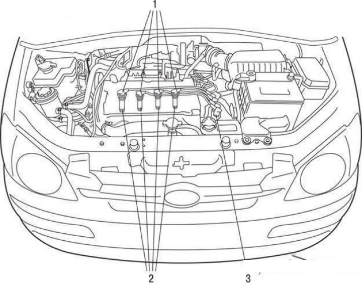
Location in the engine compartment of the ignition system components of engines with two camshafts in the cylinder head (DOHC): 1 - high-voltage wires; 2 – spark plugs; 3 – ignition coil
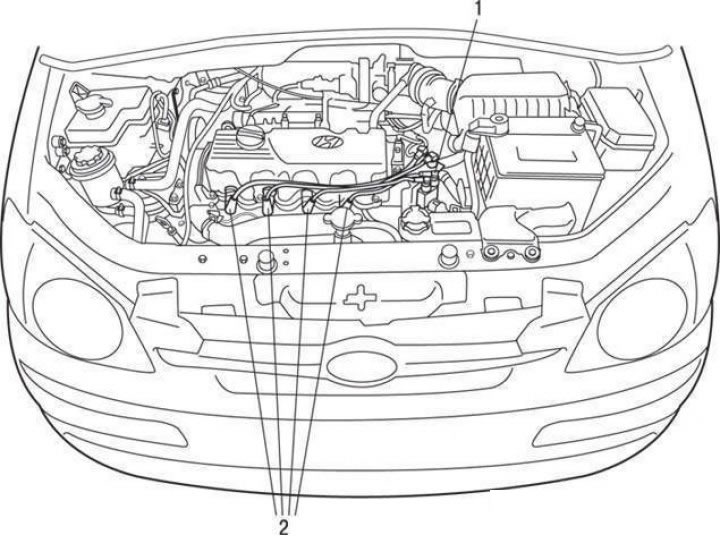
Location in the engine compartment of the ignition system components of engines with one camshaft in the cylinder head (SOHC): 1 – ignition coil; 2 – high voltage wires
The arrangement of the ignition system components in the engine compartment for engines with two camshafts in the cylinder head (DOHC) is shown in Figure 7.28. The arrangement of the ignition system components in the engine compartment for engines with one camshaft in the cylinder head (SOHC) is shown in the figure.
Ignition coil
Removal and installation
Remove the ignition system fuse (fuse link).
Disconnect the wires.
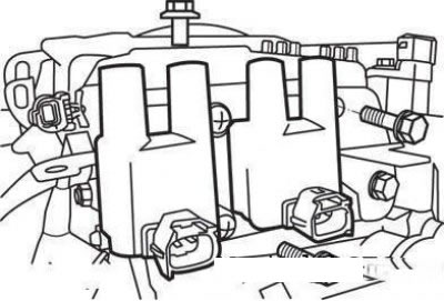
Mounting the ignition coil for engines with a working volume of 1.1 l
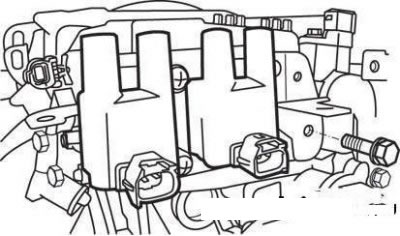
Fastening the ignition coil for engines with a working volume of 1.3, 1.5 and 1.6 liters
Remove the ignition coil by unscrewing the mounting bolt.
Installation is carried out in the reverse order of removal.
Checking the technical condition
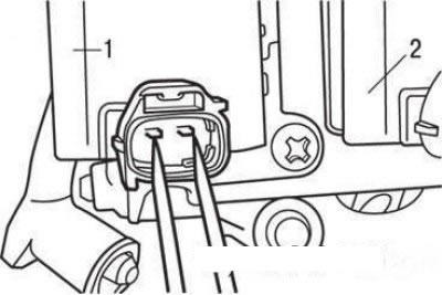
Checking the resistance of the primary winding of the ignition coil: 1 - ignition coil of the second and third cylinders; 2 – ignition coil of the first and fourth cylinders
Check the resistance of the primary winding of the coils between contacts "1" and "2".
Check the resistance of the secondary winding of the coils between the high-voltage terminals of the coil of the first and fourth cylinders and the high-voltage terminals of the second and third cylinders.
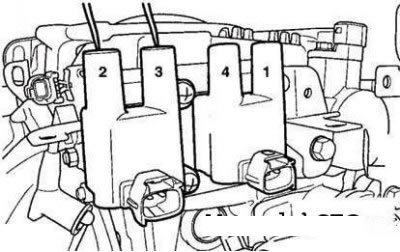
Checking the resistance of the secondary winding of the ignition coil
Nominal resistance of the secondary winding of the ignition coils is (13±15) kOhm.
Attention! Check the resistance of the secondary windings only with the ignition coil connector disconnected.
Spark plugs
Vehicle manufacturers recommend the use of a specific type of spark plug, but other types of spark plugs with the appropriate heat rating can be used.
Spark plugs should be cleaned with a sandblaster every 10,000 km of vehicle mileage. The appropriate interelectrode distance should be set. When adjusting the distance, never bend the central electrode, as this may crack its ceramic insulator.
Before removing the spark plugs, check that there are no foreign objects in the spark plug wells in the cylinder head. Any washers, bolts or small stones in the spark plug holes will destroy the valves, valve seats or cylinder head the first time the engine is started. The spark plug consists of a central electrode, an insulator with a housing and a side ground electrode. The central electrode is hermetically sealed in the insulator. The latter is firmly connected to the housing. An ignition spark jumps between the central and side electrodes, igniting the fuel-air mixture in the engine cylinder. The starting qualities of the engine, its idling behavior, throttle response and maximum speed of the car depend on the spark plug. Therefore, it is not recommended to switch from the spark plugs recommended by the manufacturer to spark plugs of a different type without special reasons. The thermal characteristic (heat rating) of the spark plug is an indicator of the degree of thermal load of the spark plug in the engine under certain operating conditions. Spark plugs are selected in such a way that they reach the self-cleaning temperature under all possible vehicle operating conditions. The lower the glow number of a spark plug, the higher its resistance to glow ignition and the lower its resistance to contamination. The higher the glow number, the lower the resistance of a spark plug to glow ignition and the higher its resistance to contamination.
The heat rating is included in the spark plug designation.
Removal
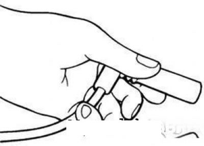
Tip of the high-tension wire of the ignition system of engines with a single camshaft in the cylinder head (SOHC)
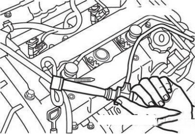
Tip of the high-tension wire of the ignition system of engines with two camshafts in the cylinder head (DOHC)
Disconnect the wires from the spark plugs.
Note: To avoid damaging the high-voltage wire, disconnect it by pulling on the wire tip, not the wire itself.
Using a spark plug wrench, remove all spark plugs from the cylinder head.
Caution! Make sure that no dirt gets into the cylinders through the spark plug holes.
Checking the technical condition
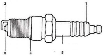
Visual inspection locations for spark plug condition
Check spark plugs for the following defects:
- damage to the insulator (point 1 in the figure);
- electrode burnout (point 2);
- carbon deposits (point 3);
- gasket damage (point 4);
- damage to the porcelain insulator at the end of the spark plug (point 5).
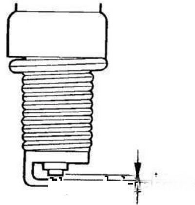
Gap (A) between spark plug electrodes
Check with a feeler gauge and, if necessary, adjust the gap A between the spark plug electrodes.
The nominal value of the gap between the spark plug electrodes (when using unleaded gasoline) is 1.0–1.1 mm.
Screw in the spark plugs by hand and tighten to a torque of 20–30 N·m.
Overtightening the spark plugs may damage the spark plug socket threads.
Determining the condition of the engine by the appearance of the spark plugs
The condition of the engine can be assessed by the color of the carbon deposits on the spark plug electrodes.
Checking spark plugs (if the engine crankshaft can be turned)
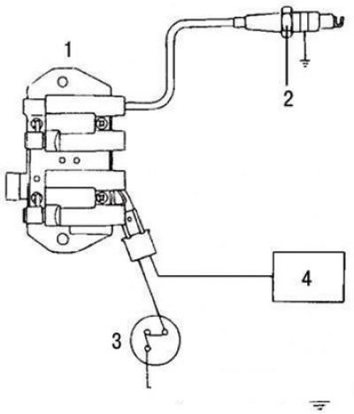
Spark plug check diagram when turning the engine crankshaft with the starter (ignition on): 1 – ignition coil; 2 – spark plug; 3 – ignition switch; 4 – electronic control unit
The diagram for checking the spark plug when turning the engine crankshaft with the starter (ignition on) is shown in the figure.
Attach the wire to the spark plug. Connect the outer electrode of the spark plug (housing) to the "ground" and turn the crankshaft. Due to the low ambient pressure, only short sparks are formed. However, if the spark plug is in good condition, spark formation should occur in the spark gap of the spark plug (between the electrodes). If the spark plug is faulty, there will be no spark formation due to current leakage through the insulator.