
Remove the automatic transmission oil pan.
Remove the oil filter.
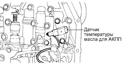
Fig. 3.77. Oil temperature sensor for automatic transmission
Remove the automatic transmission oil temperature sensor (Fig. 3.77).
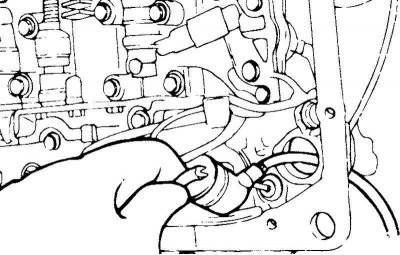
Fig. 3.78. Solenoid valve wiring harness sealing bushing retainer
Press the retaining clips of the electromagnetic valve wiring harness sealing bushing and press it into the gearbox housing (Fig. 3.78).
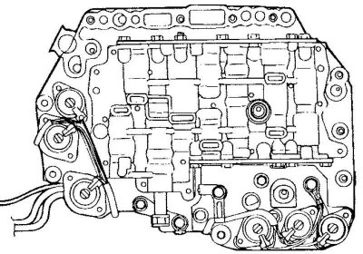
Fig. 3.79. Control valve block
Remove the control valve block assembly (valve body assembly). Range selection valve (manual valve) may fall out, so be careful not to drop the valve (Fig. 3.79).
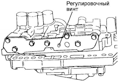
Fig. 3.80. Pressure regulator adjusting screw
Turn the pressure regulator adjusting screw and adjust the pressure in the main line (supplied to the downshift brake) (kickdown brake pressure), so that it corresponds to the nominal value (Fig. 3.80).
When turning the pressure regulator adjusting screw clockwise, the pressure in the main line decreases; when turning the adjusting screw counterclockwise, it increases.
Nominal value: 860–900 kPa.
Oil pressure change with each turn of the adjusting screw: 38 kPa.
Check that the O-ring is properly installed on the top surface of the control valve block.
Replace the solenoid valve wire harness grommet O-ring with a new one.
Install the control valve block into the transmission case, and then insert the solenoid valve harness sealing bushing into place from the inside. When installing, make sure that the protruding parts of the connector are positioned as shown in Figure 3.78. Be careful not to pinch the wires.
Tighten the control valve block assembly mounting bolts to 10–12 N·m.
Install the automatic transmission oil filter.
Install a new oil pan gasket and oil pan.
Fill the nominal amount of oil (ATF) into the automatic transmission.
Check the pressure in the automatic transmission control hydraulic system. Repeat the pressure adjustment if necessary.