
Removal
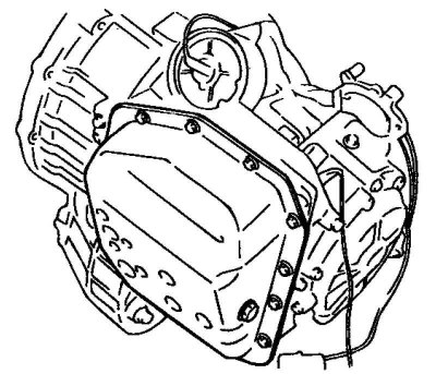
Fig. 3.98. Gearbox oil pan
Unscrew the drain plug and drain the automatic transmission fluid (ATF) from the gearbox (Fig. 3.98).
Remove the air filter housing assembly.
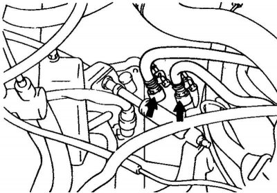
Fig. 3.99. Clamps for the oil cooler outlet and inlet hoses
Remove the clamps and disconnect the outlet and inlet hoses of the automatic transmission oil cooler (Fig. 3.99).
Note: After disconnecting the hoses, it is necessary to plug the holes in the hoses and fittings of the gearbox to prevent dust or foreign particles from getting into them.
Remove the automatic transmission control cable.
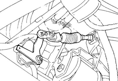
Fig. 3.100. Speedometer drive cable
Remove the speedometer drive cable (Fig. 3.100).
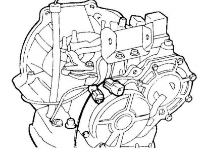
Fig. 3.101. Connectors of the starter interlock switch, electromagnetic valves and automatic transmission oil temperature sensor
Disconnect the connectors of the starter lock switch (automatic transmission selector switch), electromagnetic valves, automatic transmission oil temperature sensor, and the downshift brake servo switch (Kickdown servo switch) (Fig. 3.101).
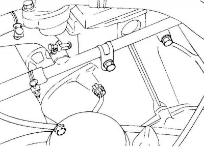
Fig. 3.102. Gearbox to engine mounting bolt
Unscrew the gearbox mounting bolt to the engine, located on the top of the gearbox (Fig. 3.102).
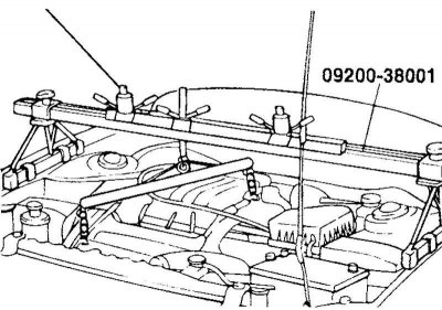
Fig. 3.103. Fastening the engine to the crossmember
Secure the engine to a special device (crossbar 09200-38001) using the mounting brackets (Fig. 3.103).
Raise the car on a lift.
Disconnect the tie rod ends, lower suspension arm ball joints and remove the wheel drive shafts. Remove the steering gear and anti-roll bar.
Disconnect the steering shaft universal joint.
Note: Mark the relative positions of the steering shaft universal joint and steering gear shaft before disconnecting them to facilitate subsequent assembly.
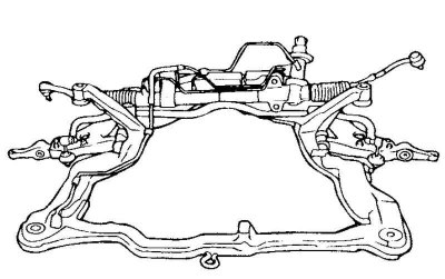
Fig. 3.104. Subframe mounting bolts
Loosen the mounting bolts and remove the subframe (Fig. 3.104).
Remove the starter.
Loosen the gearbox mounting bolts.
Loosen the bolts securing the gearbox to the engine.
Remove the gearbox assembly using a transmission telescopic jack (T/M jack).
Caution! The engine and gearbox mounts must be installed in a specific order.
The order of installation of support brackets
Side engine mount bracket.
Gearbox support bracket.
Rear engine mount bracket.
Front engine mount bracket.
Caution! Be careful when installing the front engine mount bracket, do not damage or deform the mount. If the mount is damaged, strong vibration of the power unit may occur when the engine is idling.
Installation
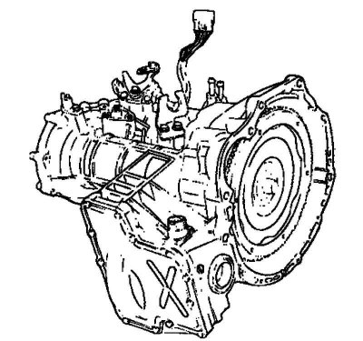
Fig. 3.105. Gearbox assembly
Connect the torque converter on the gearbox side and install the gearbox assembly on the engine (Fig. 3.105).
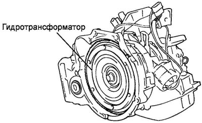
Fig. 3.106. Torque converter
Caution! If the torque converter is first installed on the engine, the gearbox seal will be damaged when installing the gearbox. Therefore, always install the torque converter on the gearbox side before assembling the power unit (Fig. 3.106).