
Contents: Checking the selector lever ⇓ Locking Cam Installation Procedure ⇓ Adjustment procedure for the…⇓ Procedure for checking the correct…⇓ Maintenance instructions ⇓ Installing the ignition key lock…⇓ Assembly of the ignition switch and…⇓ Assembling the ignition key lock…⇓
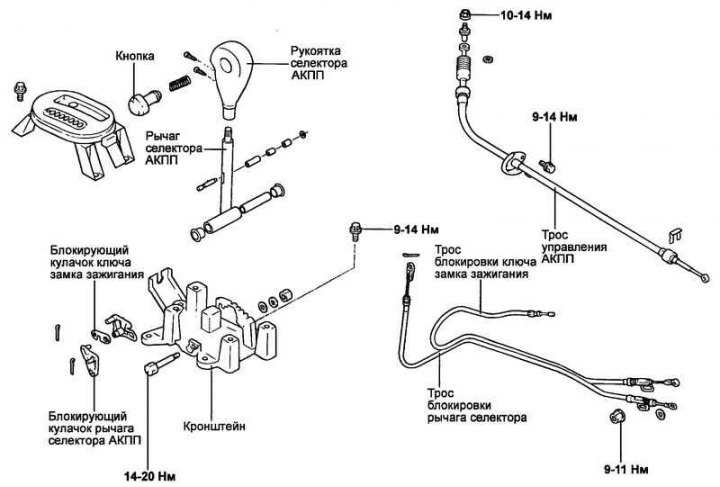
Fig. 3.107. Automatic transmission control mechanism
Checking the selector lever
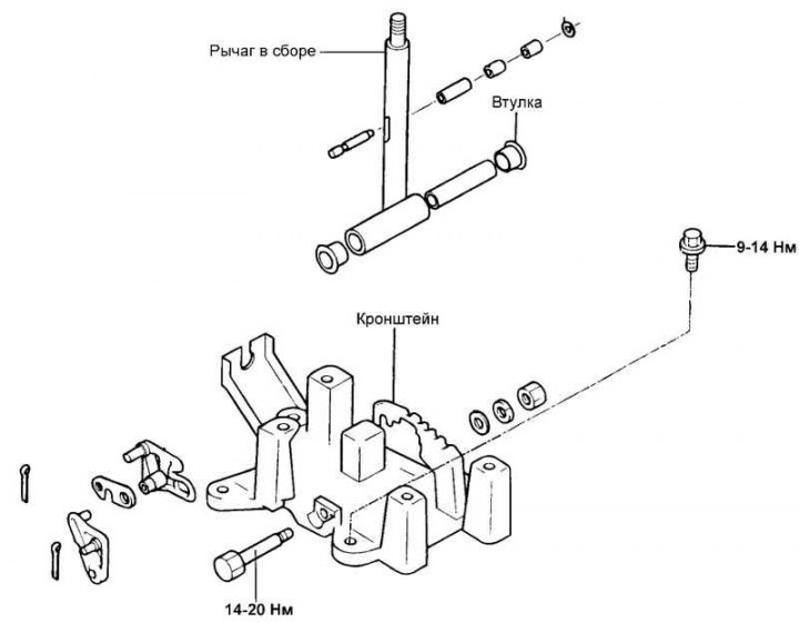
Fig. 3.108. Selector lever
Check the cam stops and cam stops for wear.
Check the automatic transmission selector lever bushings for wear or damage.
Check the spring for damage or wear.
Check the rod tip assembly for wear.
Note: When servicing the shift lever lock system, follow the instructions and adjustment procedures below to ensure proper operation of the system.
Locking Cam Installation Procedure
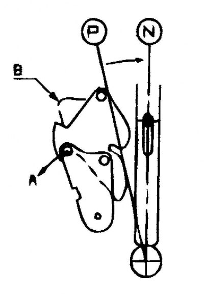
Fig. 3.109. Setting the locking cam of the ignition key is in position "B"
Move the locking cam of the automatic transmission selector lever in direction "A" and hold it with your hand in this position (see Fig. 3.109).
Check that the ignition key locking cam is in position "B" and is held in place by the stop pin (Fig. 3.109).
Adjustment procedure for the selector lever lock cable and ignition key lock cable
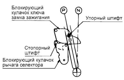
Fig. 3.110. Position of locking cams
Check that both locking cams are set to the position shown in Figure 3.110.
Install the selector lever lock cables and ignition key lock cables in the specified position. The other end of the ignition key lock cable should be fixed in the ignition switch, and the selector lever lock cable should be on the brake pedal in the corresponding position.
Temporarily connect both cables to the automatic transmission selector lever, as shown in Figure 3.111.
Securely attach each cable to the pin of the corresponding locking cam.
Check that the end of the selector lever lock cable contacts the pin of the selector lever locking cam, then secure the outer cable sheath to the bracket with a nut and the end of the cable with a washer and cotter pin.
Press the ignition key locking cam lightly in the direction indicated by arrow "Q".
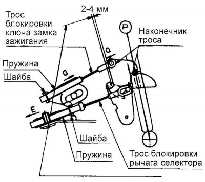
Fig. 3.111. Selector lever cables
Pull the ignition key lock cable slightly in the direction indicated by arrow "G" to tighten the cable, and then secure the outer sheath of the cable with the nut (see Fig. 3.111).
Make sure that the ignition key lock cable end is inserted onto the ignition key lock cam pin and then secure it with the washer and stopper. At the same time, check that the selector lever lock cable is secured to the selector lever lock cam as shown in Figure 3.112.
Procedure for checking the correct installation of the automatic transmission selector lever lock
When the automatic transmission selector lever is in the "P" position, the lock button on the lever cannot be pressed when the brake pedal is released (the automatic transmission selector lever cannot be moved from the "P" position to another position). The lock button operates in other positions of the automatic transmission selector lever (except "P").
If the brake pedal is pressed (pedal travel within 15–25 mm) when the automatic transmission selector lever is in the "P" position, the lock button operates without restrictions and the selector lever moves smoothly from the "P" position to another position.
If the brake pedal is released, the automatic transmission selector lever moves smoothly, without sticking, to the "P" position from any other position.
The brake pedal should move smoothly into all positions without sticking.
When the ignition key is in the "LOCK" position, the lock button on the automatic transmission selector lever is activated even when the brake pedal is released.
The ignition key does not turn to the "LOCK" position when the automatic transmission selector lever is set to a position other than "P".
If the automatic transmission selector lever is set to the "P" position, the ignition key turns to the "LOCK" position without jamming.
Maintenance instructions
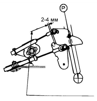
Fig. 3.112. Checking the selector lever lock cable
Pull the selector lever lock cable slightly in the direction indicated by arrow "E" to create a gap of 2-4 mm between the locking cams of the ignition key and the automatic transmission selector lever, and then secure the outer sheath of the cable to the bracket with the nut. Then check that the gap is within the range of 2-4 mm (see Fig. 3.112).
Note: If the specified clearance is not within the range of 2–4 mm, press the brake pedal harder than required to allow the automatic transmission selector lever to be moved from the "P" position to another position.
Check that there is no slack in the ignition key lock cable.
Note: If the ignition key interlock cable is loose, the ignition key cannot be removed from the ignition lock cylinder and the automatic transmission selector lever may move from the "P" position to another position, even if the ignition key is in the "LOCK" position.
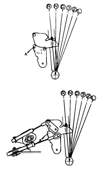
Fig. 3.113. Position of the locking cams of the ignition key and selector lever
Before and after performing the above procedures, the locking cams of the ignition switch key and selector lever must not be in the same position, as shown in Figure 3.113.
Note: If the locking cams of the ignition key and the selector lever are in the same position, then moving the automatic transmission selector lever from position "D", "3", "2", "L" to position "P", "R", "N" with force may damage the corresponding parts.
Move the automatic transmission selector lever from position "D", "3", "2", "L" to position "P", "R", "N" after turning the locking cam of the ignition key in the direction indicated by arrow "A".
Move the automatic transmission selector lever from position "D", "3", "2", "L" to position "P", "R", "N" after turning the selector lever locking cam in the direction indicated by arrow "A" with the brake pedal depressed.
Installing the ignition key lock device
A situation may arise where the ignition key cannot be removed from the ignition lock cylinder due to improper installation of the key interlock cable. To prevent this situation from occurring, follow the instructions below when performing maintenance.
Assembly of the ignition switch and ignition key lock cable
The lock assembly is installed on the steering column. Set the ignition lock cylinder on the steering column lock to the "LOCK" position.
Connect the key lock cable to the ignition switch and secure with the set screw.
Assembling the ignition key lock cable and the automatic transmission selector lever
Set the automatic transmission selector lever to position "P".
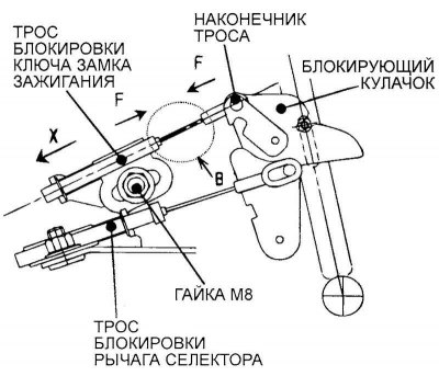
Fig. 3.114. Ignition key lock cable connection diagram
Connect the ignition key lock cable as shown in Figure 3.114, then temporarily secure the outer sheath of the cable with a nut (M8) so that the adjusting plate of the outer sheath of the cable moves with the retraction force of the latter.
While holding the ignition key interlock cable end and the outer cable sheath adjustment plate, move them in the direction indicated by arrows "F" so that there is no bend or slack in the cable at section "B".
Note: Do not pull the cable in the direction indicated by the arrow "X" to remove slack in the cable. This may result in the ignition key not being removed from the ignition cylinder.
Tighten the nut (M8) securing the ignition key lock cable.