
Contents: Locking Cam Installation Procedure ⇓ Adjustment procedure for the…⇓ Procedure for checking the correct…⇓
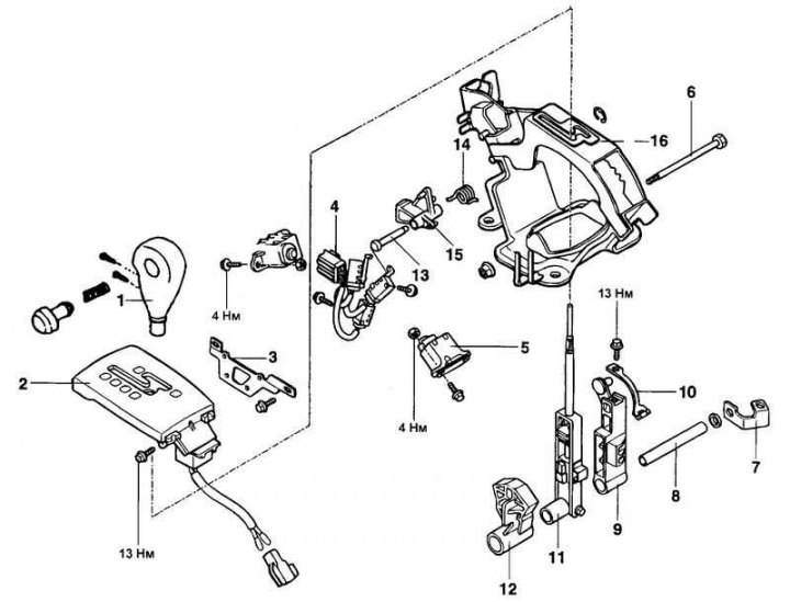
Fig. 3.92. Automatic transmission control mechanism: 1 – Automatic transmission selector lever handle; 2 – Automatic transmission selector lever position indicator panel; 3 – switch mounting bracket; 4 – magnetic switch; 5 – stopper; 6 – bolt; 7 – Parking brake cable bracket; 8 – shaft; 9 – automatic transmission control cable lever; 10 – stopper spring; 11 – automatic transmission selector lever assembly; 12 – switch lever; 13 – pin (with a hole for a cotter pin); 14 – return spring; 15 – locking cam of the automatic transmission selector lever; 16 – bracket assembly
Locking Cam Installation Procedure
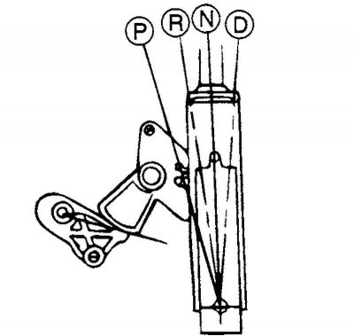
Fig. 3.93. Position of the ignition lock cam
Move the automatic transmission selector lever to the "P" position and set the ignition key locking cam as shown in the figure (Fig. 3.93).
Check that the ignition key locking cam is in position "B" and is held in place by the locking pin.
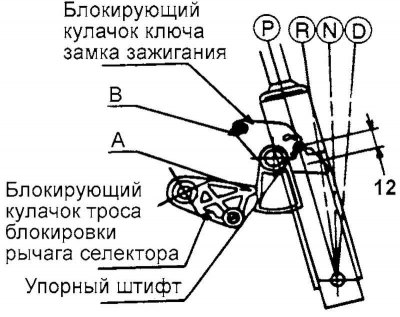
Fig. 3.94. Checking the ignition lock cam
Check that the automatic transmission selector lever locking cam is in position "A" (Fig. 3.94).
Check that the ignition switch is in the "LOCK" position.
Adjustment procedure for the selector lever lock cable and ignition key lock cable
Check that both locking cams are set to the position as shown in the figure.
Install the selector lever lock cable and the ignition key lock cable in the specified position. The other end of the ignition key lock cable must be fixed in the ignition switch, and the selector lever lock cable must be fixed on the brake pedal in the corresponding position.
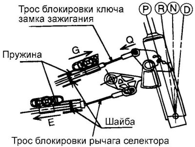
Fig. 3.95. Connecting the cables to the automatic transmission selector lever
Temporarily connect both cables to the automatic transmission selector lever as shown in Figure 3.95. Securely fasten each cable to the pin of the corresponding locking cam.
Pull the selector lever lock cable slightly in the direction indicated by arrow "E".
Check that the end of the selector lever lock cable contacts the locking pin, then secure the outer sheath of the cable to the bracket using the self-tapping bolt (self-tapping bolt).
Press the ignition key locking cam lightly in the direction indicated by arrow "Q".
Pull the ignition key interlock cable slightly in the direction indicated by arrow "G" to tighten the cable, and then secure the outer casing of the cable with the nut.
Check that the ignition key lock cable end and the selector lever lock cable are secure.
Procedure for checking the correct installation of the automatic transmission selector lever lock
When the automatic transmission selector lever is in the "P" position, the lock button on the lever cannot be pressed when the brake pedal is released (the automatic transmission selector lever cannot be moved from the "P" position to another position).
If the brake pedal is pressed (pedal travel within 15–22 mm) when the automatic transmission selector lever is in the "P" position, the lock button should operate without restrictions and the selector lever can be smoothly moved from the "P" position to another position.
If the brake pedal is released, the automatic transmission selector lever should move smoothly, without sticking, to the "P" position from any other position.
The brake pedal should move smoothly, without sticking.
When the ignition key is in the "LOCK" position, even with the brake pedal released, the lock button on the automatic transmission selector lever should operate.
The ignition switch must not be turned to the "LOCK" position when the automatic transmission selector lever is in a position other than "P".
If the automatic transmission selector lever is set to the "P" position, the ignition key should easily turn to the "LOCK" position without sticking.