
Contents: Adjusting the axial clearance of the…⇓ Adjusting the axial clearance of the…⇓ Adjusting the axial clearance of the…⇓ Adjusting the axial clearance of the…⇓ Adjusting the differential housing…⇓
Adjusting the axial clearance of the brake thrust disc (Brake reaction plate end play)
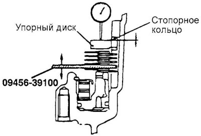
Fig. 3.75. Scheme of adjustment of axial clearance of the brake thrust disc
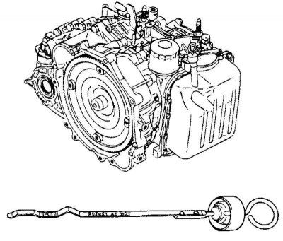
Fig. 3.60. Oil dipstick
Replace the pressure plate (pressure plate) brakes of first gear and reverse gear with a special device and then install the disc with linings (brake disk), disc without linings (brake plate) and the retaining ring as shown in Figure 3.60. Install the thrust disc and the original retaining ring removed earlier. Measure the axial clearance by moving the special device and then, if the axial clearance does not correspond to the nominal value, adjust it by replacing the original retaining ring with a new one of the appropriate thickness.
Nominal value: 0.0-0.16mm (See reference table 3.20).
Adjusting the axial clearance of the second gear brake (Second brake end play)
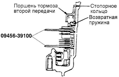
Fig. 3.76. Second gear brake axial clearance adjustment diagram
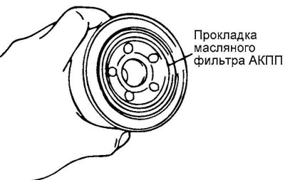
Fig. 3.61. Oil filter gasket
Replace the pressure plate (pressure plate) brakes of the second gear with a special device and then install the disc with linings (brake disk), disc without linings (brake plate), as shown in Figure 3.61. Install the return spring (return spring), second gear brake piston (second brake piston) and a retaining ring.
Nominal value: 0.79–1.25 mm.
If the axial clearance does not correspond to the nominal value, then adjust it by selecting a new pressure plate, the thickness of which corresponds to the specified range of values.
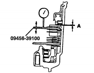
Fig. 3.77. Second gear brake axial clearance
Thickness of the new pressure plate = (measured clearance "A") + (thickness of the special device) – (nominal value of the axial clearance) (Fig. 3.77).
See help table 3.20.
Adjusting the axial clearance of the first gear and reverse gear brakes
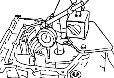
Fig. 3.78. Measuring the axial clearance of the first gear brake
Turn the gearbox upside down and install a dial indicator (Fig. 3.78).
Measure the axial clearance by moving the special device up and down.
Nominal value: 1.35–1.81 mm.
If the axial clearance does not correspond to the nominal value, then adjust it by selecting a new pressure plate, the thickness of which corresponds to the specified range of values.
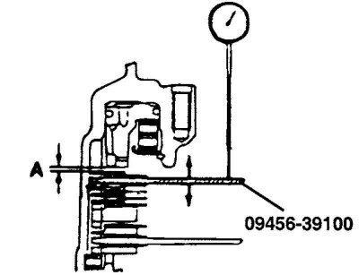
Fig. 3.79. Axial clearance of the first gear brake
Thickness of the new pressure plate = (measured clearance "A") + (thickness of the special device) – (nominal value of the axial clearance) (Fig. 3.79).
See help table 3.20.
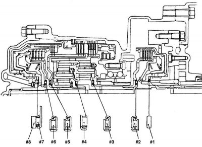
Fig. 3.80. Identification of thrust bearings
Adjusting the axial clearance of the sun gear of the reduction planetary row (underdrive sun gear end play)
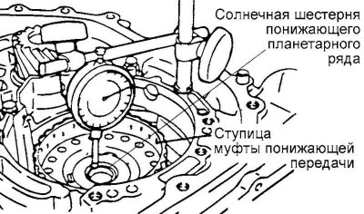
Fig. 3.81. Measuring the axial clearance of the sun gear of the reduction planetary gear set
Install the previously removed original thrust bearing race #8, then install the rear cover of the gearbox housing. Measure the axial clearance of the sun gear of the reduction planetary row (Fig. 3.81).
If the axial clearance does not correspond to the nominal value, then adjust it by selecting a new thrust bearing race according to the table provided #8 of the corresponding thickness.
Nominal value: 0.25–0.45 mm.
Note: To simplify the measurement of the axial clearance of the underdrive sun gear, install the underdrive clutch hub.
Adjusting the differential housing preload (Differential case preload)
Place a piece of soft solder (approximately 10 mm long and approximately 3 mm in diameter) on the torque converter housing.
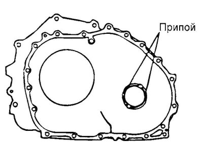
Fig. 3.82. Solder extraction
Install the torque converter housing onto the gearbox housing without using sealant. Tighten the mounting bolts to the specified torque. Loosen the mounting bolts and remove the solder (Fig. 3.82).
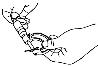
Fig. 3.83. Measuring the thickness of a deformed piece of solder
Using a micrometer, measure the thickness "T" of the deformed solder piece. To create the nominal preload, select a spacer whose thickness corresponds to the specified range of values (Fig. 3.83).
Nominal value: 0.045–0.105 mm.
Spacer thickness = (solder thickness "T") + (nominal preload value)