HyundaiBook.ru
Repair Chevrolet Repair Honda Repair Toyota Repair Land Rover Repair VAZ Repair Renault Repair Nissan
English Русский
Български
Беларускі
Український
Српски
Hrvatski
Română
Polski
Slovenský
Magyar
ArticlesSitemapContacts  


  Accent   Elantra   Getz   Grandeur   Sonata   Santa Fe   Tucson   Others
Santa Fe 2 (2007-2012, petrol)
  • Main
  • Santa Fe
  • CM (2007-2012)
  • Transmission
  • Automatic gearbox
  • Checking the components of the automatic transmission control system

Checking the components of the automatic transmission control system (Hyundai Santa Fe CM)

0
Contents: Checking the Throttle Position…⇓ Checking the automatic transmission…⇓ Nominal value ⇓ Checking the vehicle speed sensor…⇓ Checking the automatic transmission…⇓ Checking the electromagnetic valves ⇓

Checking the Throttle Position Sensor (TPS)


The throttle position sensor is a potentiometer with a sliding contact that moves in accordance with the rotation of the throttle axis, indicating the opening angle of the valve. When the throttle axis rotates, the signal voltage of the throttle position sensor changes. Based on the change in the value of the sensor signal voltage and the rate of its change, the electronic engine control unit determines the degree and speed of opening of the throttle valve.

Checking the automatic transmission oil temperature sensor


Fig. 3.67. Automatic transmission oil…

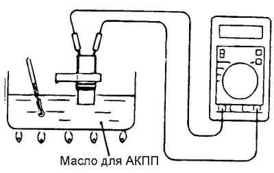
Fig. 3.67. Automatic transmission oil temperature sensor test diagram


Remove the automatic transmission oil temperature sensor.

Measure the resistance between terminals 1 and 2 of the sensor connector at the test points.

Nominal value


Nominal value

[The text is provided by the web resource HyundaiBook]


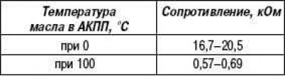
Checking the vehicle speed sensor (vehicle speed sensor)


Fig. 3.68. Vehicle speed sensor test…

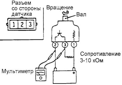
Fig. 3.68. Vehicle speed sensor test diagram


Remove the vehicle speed sensor and connect a 3-10 kOhm resistor to it, as shown in Figure 3.68.

Rotate the vehicle speed sensor shaft to ensure that voltage appears at terminals 2–3 of the sensor connector (4 pulses per revolution).

Checking the automatic transmission control relay (a/t control relay)


Fig. 3.69. Automatic transmission…

Fig. 3.69. Automatic transmission control relay test diagram


Fig. 3.69. Automatic transmission…

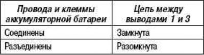
Remove the automatic transmission control relay.


Using wires with a crocodile clip connector (jumper wires) connect terminal 2 of the automatic transmission control relay to the positive (+) terminal of the battery, and terminal 4 to the negative (–) terminal.

Check the condition of the circuit between terminals 1 and 3 of the control relay with the wires connected and disconnected from the battery terminals.

If the relay operation differs from that specified, replace the automatic transmission control relay.

Checking the electromagnetic valves


Fig. 3.70. Electromagnetic valve…

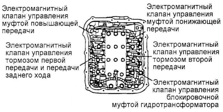
Fig. 3.70. Electromagnetic valve testing diagram


Remove the control valve housing cover.

Disconnect the connectors from each solenoid valve.

Fig. 3.71. Measuring the resistance…

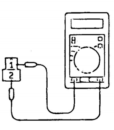
Fig. 3.71. Measuring the resistance between terminals 1 and 2 of each solenoid valve


Measure the resistance between terminals 1 and 2 of each solenoid valve (Fig. 3.71).

If the resistance is outside the standard value, replace the solenoid valve.

Fig. 3.72. Control valve block…

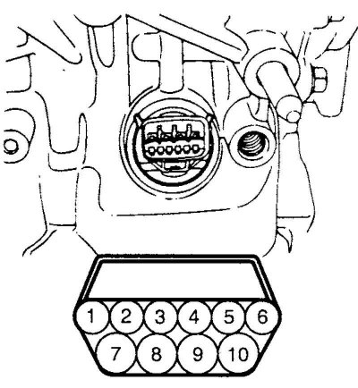
Fig. 3.72. Control valve block connector terminals


Note: Resistance at the terminals of the control valve block connector (Fig. 3.72).
This article is available at russian, bulgarian, belarusian, ukrainian, serbian, croatian, romanian, polish, slovak, hungarian
This article has been reviewed by: Konstantin Smirnov
Add to social network:

Previous
Santa Fe 2: Automatic gearbox
Next

Checking the starter interlock switch circuits (automatic transmission selector switch)
Basic checks and adjustments on the car
Testing the torque converter on a fully braked vehicle (Torque converter stall test)
Analysis of the test results on a fully braked vehicle
Checking the pressure in the hydraulic control system of the automatic transmission
Automatic transmission self-diagnosis function
Technical operations on a gearbox removed from a vehicle
We recommend other articles on the topic of Hyundai manuals:

Checking the elements of the automatic transmission control… Hyundai Accent 3 (2005-2010)
Scheme 5. Automatic transmission control system after 1995 Hyundai Elantra 1 (1990-1995, petrol)
Checking the fluid level in the automatic transmission Hyundai Getz (2002-2011)
Electrical diagram of the automatic transmission control system Hyundai Sonata 4 (2001-2012, petrol)
Automatic lighting control unit — checking the technical… Hyundai Tucson 1 (2005-2010)
Checking the components of the automatic transmission control… Hyundai Matrix (2001-2010, petrol)

Link in different formats to this article

Visitor comments
No comments yet


How much will 49 + 41 ?


Santa Fe 2 (2007-2012, petrol) 
  • User manual
  • Control devices
  • Heating and ventilation
  • Seat control
  • Car driving
  • Maintenance and care
  • Vehicle Specifications
  • Engine 2.0 and 2.4 liters
  • Engine specifications
  • Engine maintenance
  • Engine repair
  • Cooling system
  • Intake and exhaust system
  • Fuel system
  • Engine 2.7 liter
  • Engine maintenance
  • Engine repair
  • Cooling system
  • Intake and exhaust system
  • Transmission
  • Transmission specifications
  • Mechanical gearbox
  • Automatic gearbox
  • Drive shafts
  • Chassis
  • Suspension and wheels
  • Steering
  • Brake system
  • Body
  • Exterior (external elements)
  • Electrical equipment
  • Equipment and devices
  • Power devices
  • Specifications
HyundaiBook.ru © 2018-2026 · Mobile version · Sitemap: EN BG BY UA RS HR RO PL SK HU · Administration · Site search · Hyundai owners Accent 1 · Accent 2 · Accent 3 · Elantra 1 · Elantra 2 · Elantra 3 · Getz · Sonata 3 · Sonata 4 · Santa Fe 2 · Tucson 1 · Tucson 2 · Matrix ·
This site uses cookies to optimize its functionality. By continuing, you agree to our terms.