
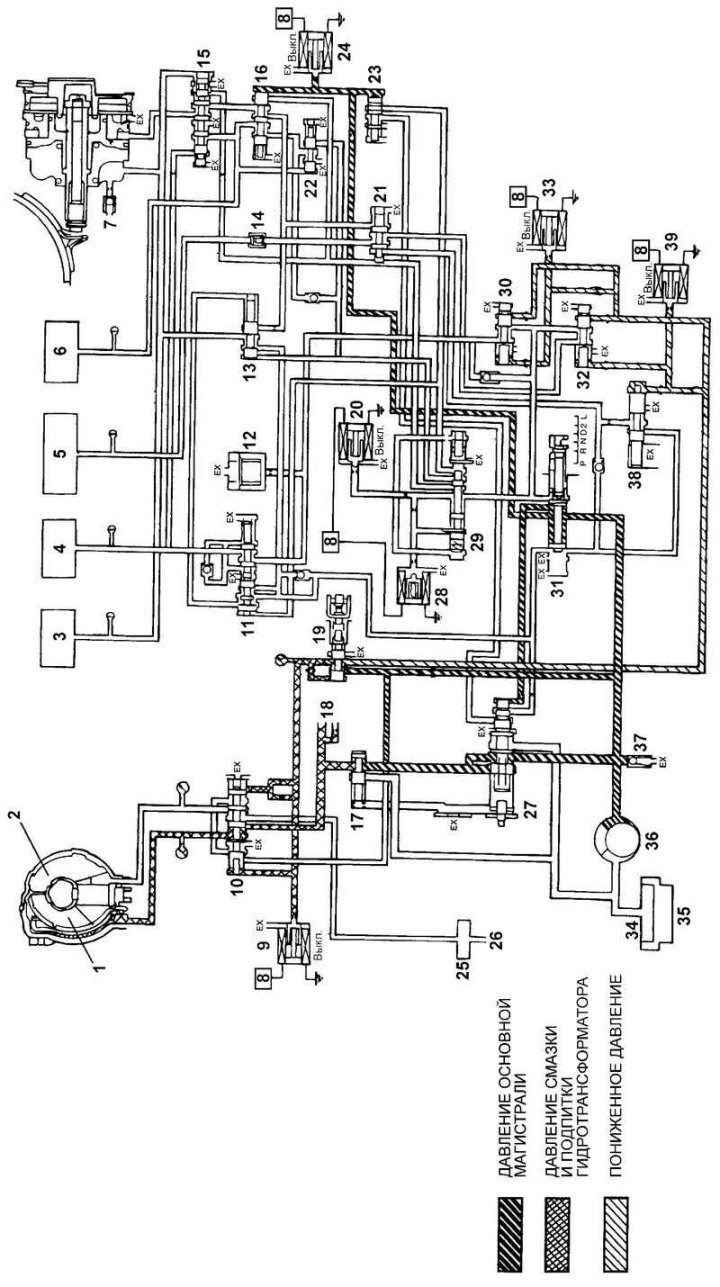
Fig. 3.85. Hydraulic diagram of the automatic transmission control system, positions "N" (neutral) and "P" (parking): 1 – torque converter lock-up clutch; 2 – torque converter; 3 – front clutch; 4 – rear clutch; 5 – first gear and reverse gear brake; 6 – outer sleeve; 7 – servo drive of the forced downshift brake; 8 – electronic transmission control unit (TCU); 9 – electromagnetic valve for controlling the torque converter lock-up clutch; 10 – torque converter lock-up clutch control valve; 11 – rear clutch valve; 12 – hydraulic accumulator; 13 – 2–3 and 4–3 switching valve; 14 – first gear and reverse gear brake valve; 15 – emergency mode valve; 16 – switching valve; 17 – torque converter control valve (TC); 18 – to the lubrication system of the rear part of the automatic transmission; 19 – pressure reducing valve; 20 – electromagnetic valve "A" for switching control; 21 – 1–2 switching valve; 22 – outer clutch control valve; 23 – overdrive pressure control valve (HIGH-LOW); 24 – electromagnetic valve "C" for switching control; 25 – automatic transmission oil cooler; 26 – to the lubrication system of the front part of the automatic transmission; 27 – pressure regulator; 28 – electromagnetic valve "B" for switching control; 29 – gear shift control valve; 30 - additional pressure regulator "B"; 31 – range selection valve; 32 – additional pressure regulator "A"; 33 – electromagnetic valve "B" for pressure regulation; 34 – Automatic transmission oil filter; 35 – automatic transmission oil pan; 36 – automatic transmission oil pump; 37 – safety valve; 38 – N-R shift quality control valve; 39 – electromagnetic valve "A" for pressure regulation
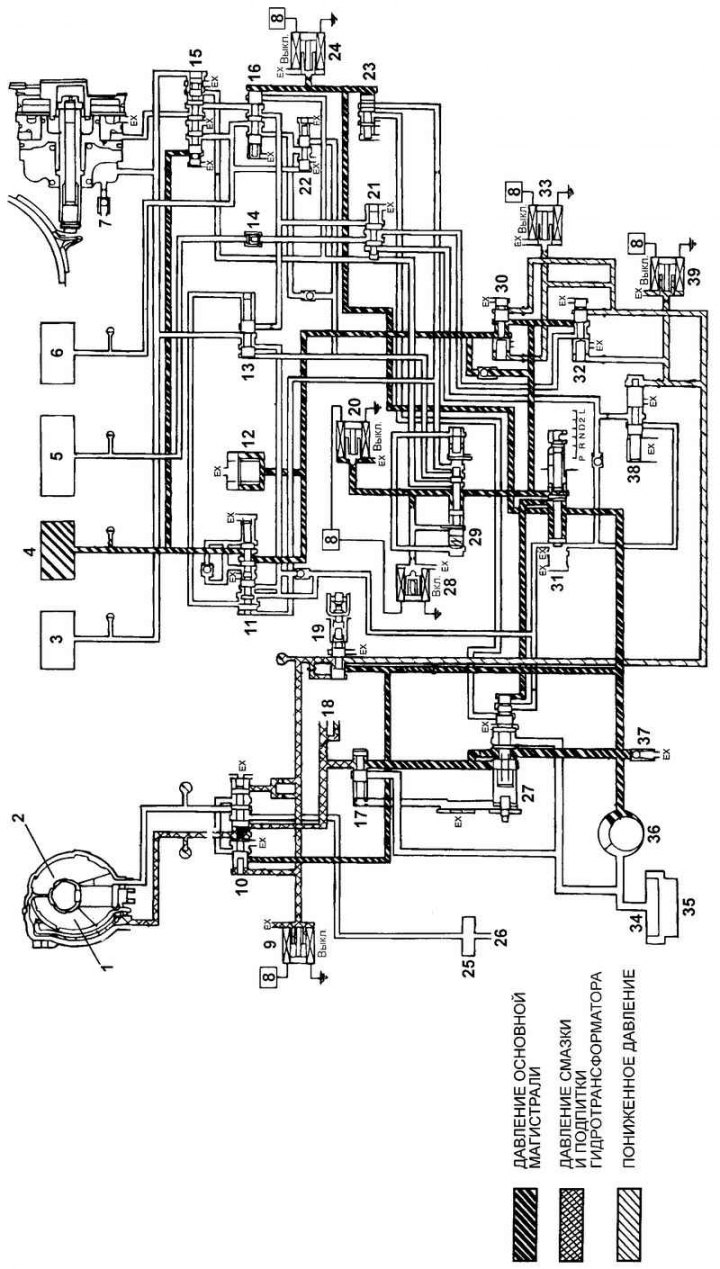
Fig. 3.86. Hydraulic diagram of the automatic transmission control system, position "D" (1st gear): 1 – torque converter lock-up clutch; 2 – torque converter; 3 – front clutch; 4 – rear clutch; 5 – first gear and reverse gear brake; 6 – outer sleeve; 7 – servo drive of the forced downshift brake; 8 – electronic transmission control unit (TCU); 9 – electromagnetic valve for controlling the torque converter lock-up clutch; 10 – torque converter lock-up clutch control valve; 11 – rear clutch valve; 12 – hydraulic accumulator; 13 – 2–3 and 4–3 switching valve; 14 – first gear and reverse gear brake valve; 15 – emergency mode valve; 16 – switching valve; 17 – torque converter control valve (TC); 18 – to the lubrication system of the rear part of the automatic transmission; 19 – pressure reducing valve; 20 – electromagnetic valve "A" for switching control; 21 – 1–2 switching valve; 22 – outer clutch control valve; 23 – overdrive pressure control valve (HIGH-LOW); 24 – electromagnetic valve "C" for switching control; 25 – automatic transmission oil cooler; 26 – to the lubrication system of the front part of the automatic transmission; 27 – pressure regulator; 28 – electromagnetic valve "B" for switching control; 29 – gear shift control valve; 30 - additional pressure regulator "B"; 31 – range selection valve; 32 – additional pressure regulator "A"; 33 – electromagnetic valve "B" for pressure regulation; 34 – Automatic transmission oil filter; 35 – automatic transmission oil pan; 36 – automatic transmission oil pump; 37 – safety valve; 38 – N-R shift quality control valve; 39 - electromagnetic valve "A" for pressure regulation
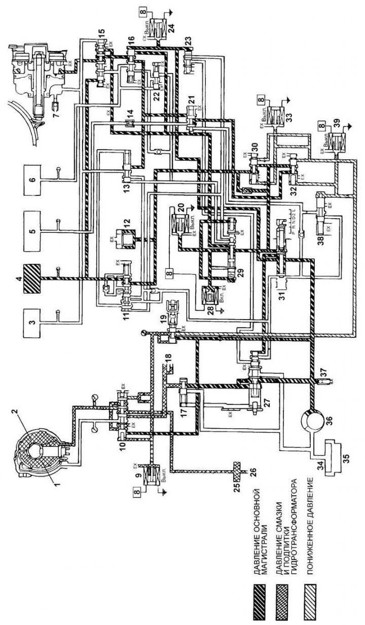
Fig. 3.87. Hydraulic diagram of the automatic transmission control system, position "D" (2nd gear): 1 – torque converter lock-up clutch; 2 – torque converter; 3 – front clutch; 4 – rear clutch; 5 – first gear and reverse gear brake; 6 – outer sleeve; 7 – servo drive of the forced downshift brake; 8 – electronic transmission control unit (TCU); 9 – electromagnetic valve for controlling the torque converter lock-up clutch; 10 – torque converter lock-up clutch control valve; 11 – rear clutch valve; 12 – hydraulic accumulator; 13 – 2–3 and 4–3 switching valve; 14 – first gear and reverse gear brake valve; 15 – emergency mode valve; 16 – switching valve; 17 – torque converter control valve (TC); 18 – to the lubrication system of the rear part of the automatic transmission; 19 – pressure reducing valve; 20 – electromagnetic valve "A" for switching control; 21 – 1–2 switching valve; 22 – outer clutch control valve; 23 – overdrive pressure control valve (HIGH-LOW); 24 – electromagnetic valve "C" for switching control; 25 – automatic transmission oil cooler; 26 – to the lubrication system of the front part of the automatic transmission; 27 – pressure regulator; 28 – electromagnetic valve "B" for switching control; 29 – gear shift control valve; 30 - additional pressure regulator "B"; 31 – range selection valve; 32 – additional pressure regulator "A"; 33 – electromagnetic valve "B" for pressure regulation; 34 – Automatic transmission oil filter; 35 – automatic transmission oil pan; 36 – automatic transmission oil pump; 37 – safety valve; 38 – N-R shift quality control valve; 39 - electromagnetic valve "A" for pressure regulation
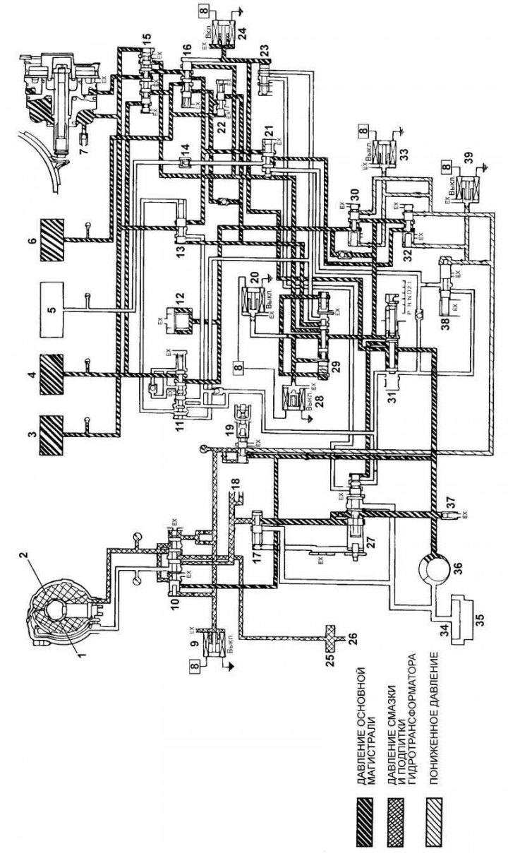
Fig. 3.88. Hydraulic diagram of the automatic transmission control system, position "D" (3rd gear): 1 – torque converter lock-up clutch; 2 – torque converter; 3 – front clutch; 4 – rear clutch; 5 – first gear and reverse gear brake; 6 – outer sleeve; 7 – servo drive of the forced downshift brake; 8 – electronic transmission control unit (TCU); 9 – electromagnetic valve for controlling the torque converter lock-up clutch; 10 – torque converter lock-up clutch control valve; 11 – rear clutch valve; 12 – hydraulic accumulator; 13 – 2–3 and 4–3 switching valve; 14 – first gear and reverse gear brake valve; 15 – emergency mode valve; 16 – switching valve; 17 – torque converter control valve (TC); 18 – to the lubrication system of the rear part of the automatic transmission; 19 – pressure reducing valve; 20 – electromagnetic valve "A" for switching control; 21 – 1–2 switching valve; 22 – outer clutch control valve; 23 – overdrive pressure control valve (HIGH-LOW); 24 – electromagnetic valve "C" for switching control; 25 – automatic transmission oil cooler; 26 – to the lubrication system of the front part of the automatic transmission; 27 – pressure regulator; 28 – electromagnetic valve "B" for switching control; 29 – gear shift control valve; 30 - additional pressure regulator "B"; 31 – range selection valve; 32 – additional pressure regulator "A"; 33 – electromagnetic valve "B" for pressure regulation; 34 – Automatic transmission oil filter; 35 – automatic transmission oil pan; 36 – automatic transmission oil pump; 37 – safety valve; 38 – N-R shift quality control valve; 39 - electromagnetic valve "A" for pressure regulation
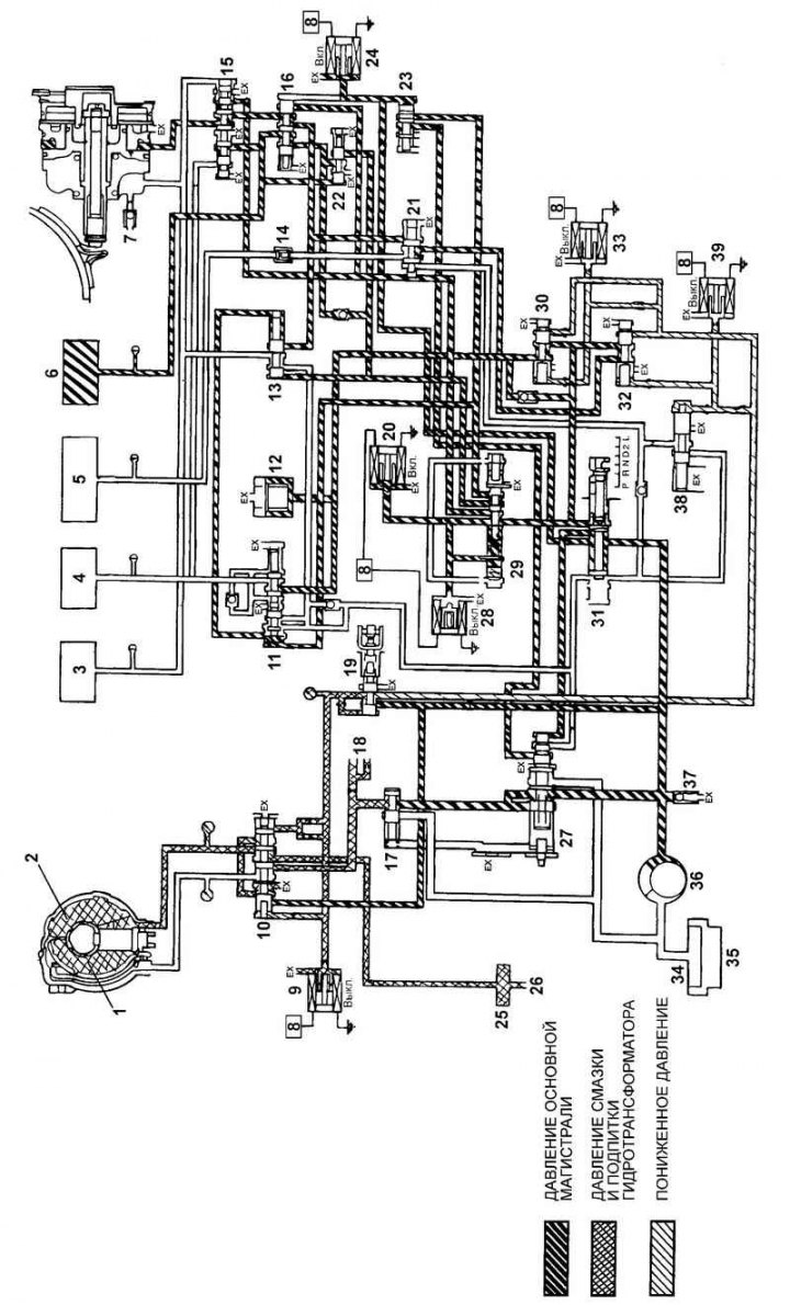
Fig. 3.89. Hydraulic diagram of the automatic transmission control system, position "D" (4th gear): 1 – torque converter lock-up clutch; 2 – torque converter; 3 – front clutch; 4 – rear clutch; 5 – first gear and reverse gear brake; 6 – outer sleeve; 7 – servo drive of the forced downshift brake; 8 – electronic transmission control unit (TCU); 9 – electromagnetic valve for controlling the torque converter lock-up clutch; 10 – torque converter lock-up clutch control valve; 11 – rear clutch valve; 12 – hydraulic accumulator; 13 – 2–3 and 4–3 switching valve; 14 – first gear and reverse gear brake valve; 15 – emergency mode valve; 16 – switching valve; 17 – torque converter control valve (TC); 18 – to the lubrication system of the rear part of the automatic transmission; 19 – pressure reducing valve; 20 – electromagnetic valve "A" for switching control; 21 – 1–2 switching valve; 22 – outer clutch control valve; 23 – overdrive pressure control valve (HIGH-LOW); 24 – electromagnetic valve "C" for switching control; 25 – automatic transmission oil cooler; 26 – to the lubrication system of the front part of the automatic transmission; 27 – pressure regulator; 28 – electromagnetic valve "B" for switching control; 29 – gear shift control valve; 30 - additional pressure regulator "B"; 31 – range selection valve; 32 – additional pressure regulator "A"; 33 – electromagnetic valve "B" for pressure regulation; 34 – Automatic transmission oil filter; 35 – automatic transmission oil pan; 36 – automatic transmission oil pump; 37 – safety valve; 38 – N-R shift quality control valve; 39 - electromagnetic valve "A" for pressure regulation
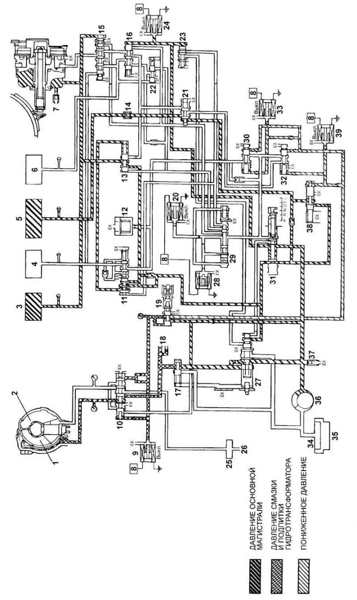
Fig. 3.90. Hydraulic diagram of the automatic transmission control system, position "R" (reverse gear): 1 – torque converter lock-up clutch; 2 – torque converter; 3 – front clutch; 4 – rear clutch; 5 – first gear and reverse gear brake; 6 – outer sleeve; 7 – servo drive of the forced downshift brake; 8 – electronic transmission control unit (TCU); 9 – electromagnetic valve for controlling the torque converter lock-up clutch; 10 – torque converter lock-up clutch control valve; 11 – rear clutch valve; 12 – hydraulic accumulator; 13 – 2–3 and 4–3 switching valve; 14 – first gear and reverse gear brake valve; 15 – emergency mode valve; 16 – switching valve; 17 – torque converter control valve (TC); 18 – to the lubrication system of the rear part of the automatic transmission; 19 – pressure reducing valve; 20 – electromagnetic valve "A" for switching control; 21 – 1–2 switching valve; 22 – outer clutch control valve; 23 – overdrive pressure control valve (HIGH-LOW); 24 – electromagnetic valve "C" for switching control; 25 – automatic transmission oil cooler; 26 – to the lubrication system of the front part of the automatic transmission; 27 – pressure regulator; 28 – electromagnetic valve "B" for switching control; 29 – gear shift control valve; 30 - additional pressure regulator "B"; 31 – range selection valve; 32 – additional pressure regulator; 33 – electromagnetic valve "B" for pressure regulation; 34 – Automatic transmission oil filter; 35 – automatic transmission oil pan; 36 – automatic transmission oil pump; 37 – safety valve; 38 – N-R shift quality control valve; 39 - electromagnetic valve "A" for pressure regulation
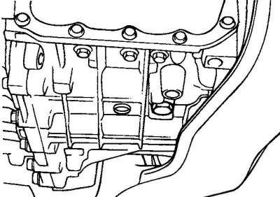
Fig. 3.91. Automatic transmission drain plug
Unscrew the drain plug and drain the automatic transmission fluid (ATF) from the gearbox (Fig. 3.91).
Remove the air filter housing assembly.
Remove the automatic transmission control cable.
Disconnect the vehicle speed sensor (speedometer) connector.
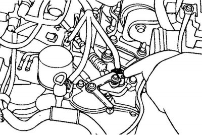
Fig. 3.92. Starter interlock switch connectors
Disconnect the connectors of the starter lock switch, the solenoid valves and the automatic transmission oil temperature (ATF) sensor (Fig. 3.92).
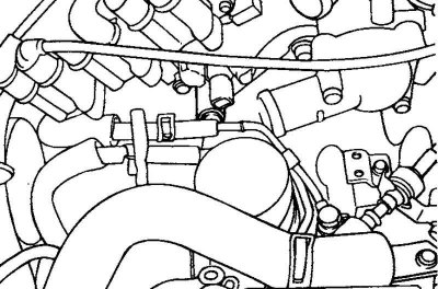
Fig. 3.93. Oil cooler hoses
Disconnect the automatic transmission oil cooler hoses (Fig. 3.93).
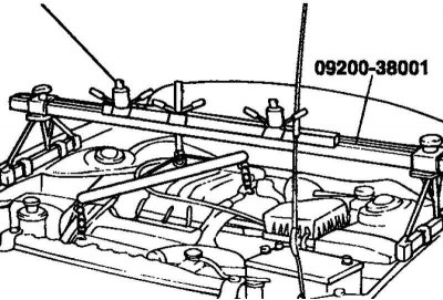
Fig. 3.94. Fastening the engine to a special device
Secure the engine to a special device (crossbar 09200-38001) using the mounting brackets (Fig. 3.94).
Raise the car on a lift.
Disconnect the tie rod ends, lower suspension arm ball joints and remove the wheel drive shafts. Remove the steering gear and anti-roll bar.
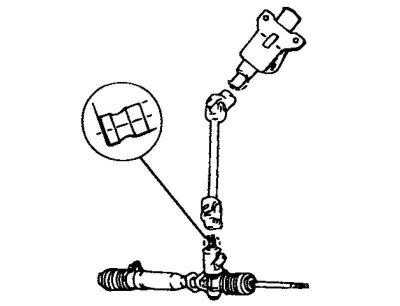
Fig. 3.95. Steering shaft cardan joint
Disconnect the steering shaft cardan joint (Fig. 3.95).
Note: Mark the relative positions of the steering shaft universal joint and steering gear shaft before disconnecting them to facilitate subsequent assembly.
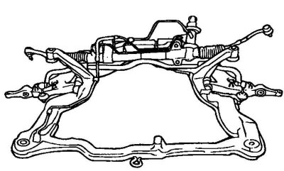
Fig. 3.96. Subframe
Loosen the mounting bolts and remove the subframe (Fig. 3.96).
Remove the starter.
Loosen the gearbox mounting bolts.
Loosen the bolts securing the gearbox to the engine.
Remove the transmission assembly using a transmission telescopic jack (T/M Jack).
Caution! The engine and gearbox mounts must be installed in a specific order.
The order of installation of support brackets
Side engine mount bracket.
Gearbox support bracket.
Rear engine mount bracket.
Front engine mount bracket.
Caution! Be careful when installing the front engine mount bracket, do not damage or deform the mount. If the mount is damaged, strong vibration of the power unit may occur when the engine is idling.
Installation
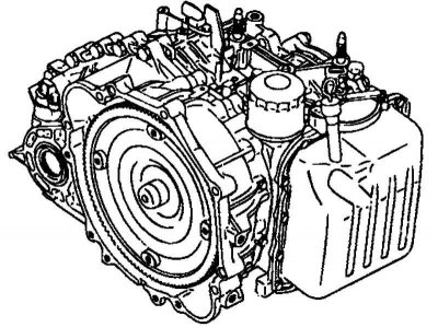
Fig. 3.97. Gearbox assembly
Connect the torque converter on the gearbox side and install the gearbox assembly on the engine (Fig. 3.97).
Caution! If the torque converter is first installed on the engine, the gearbox seal will be damaged when installing the gearbox. Therefore, always install the torque converter on the gearbox side before assembling the power unit.
Install the automatic transmission control cable and adjust it as follows in the order given below.
Move the automatic transmission selector lever and the starter interlock switch (automatic transmission selector switch) on the transmission to the "N" position, then connect the automatic transmission control cable.
The original can be read on the resource www.hyundaibook.ru
After connecting the automatic transmission control cable to the intermediate mount on the transmission support bracket, securely fasten the cable with a clamp.
Turn the adjusting nut to adjust the position of the automatic transmission control cable on the starter interlock switch (automatic transmission selector switch) so that there is no free play in the cable. Then check that the automatic transmission selector lever shifts smoothly.
Visually check the correct adjustment of the automatic transmission control cable.
The installation of the remaining parts is carried out in the reverse order of removal.