
Contents: Adjustment without using a tester ⇓ Adjustment using a tester ⇓ Replacing the wheel drive shaft seals ⇓ Replacing the speedometer drive cable ⇓
Adjustment without using a tester
Remove the components up to the oil filter in the same order as in the main line pressure adjustment procedure. Do not remove the control valve block.
Turn the adjusting screw on the bottom of the control valve block and adjust the underpressure so that it corresponds to the nominal value. When turning the adjusting screw clockwise, the underpressure decreases, when turning the adjusting screw counterclockwise, it increases.
Note: When adjusting, the reduced pressure should reach the average value (425 kPa) of the nominal value range.
Note: Nominal value: 420±20 kPa.
Oil pressure change with each turn of the adjusting screw: 22 kPa.
Install the oil filter and oil pan in the same order as the main line pressure adjustment procedure.
Check the pressure in the automatic transmission control hydraulic system. Repeat the pressure adjustment if necessary.
Adjustment using a tester
Using the ACTUATOR TEST mode of the tester, force the cycle duty cycle to 50% (50% duty) pressure control solenoid valve (PCSV) and measure the pressure supplied to the downshift brake at that time.
If the pressure supplied to the downshift brake (kickdown brake pressure), does not correspond to the nominal value range, adjust the pressure using the adjusting screw.
Nominal value: 320±30 kPa.
Change in oil pressure with each turn of the adjusting screw: 30 kPa.
Check that after completing this adjustment, the reduced pressure value (reducing presure) corresponds to the range of 370–490 kPa.
Attention! Adjustment should be made at an oil temperature (ATF) in the automatic transmission of 70–80°C. If adjustment is made at too high an oil temperature (ATF) in the automatic transmission, the pressure in the main line will drop when the engine is idling, and as a result, it will be impossible to perform correct adjustment.
Replacing the wheel drive shaft seals
Disconnect the wheel drive shaft from the gearbox.
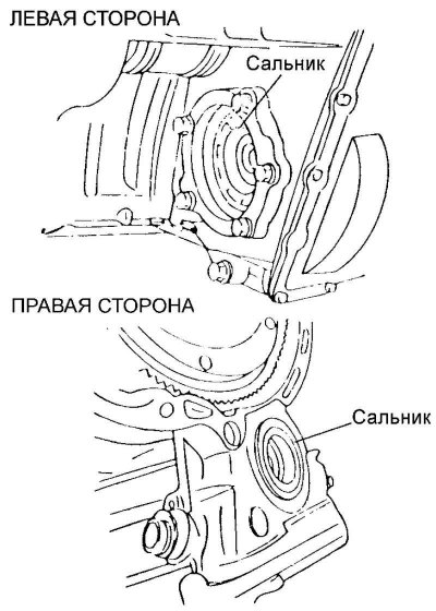
Fig. 3.81. Wheel cable shaft seals
Using a flat-head screwdriver, remove the seal (Fig. 3.81).
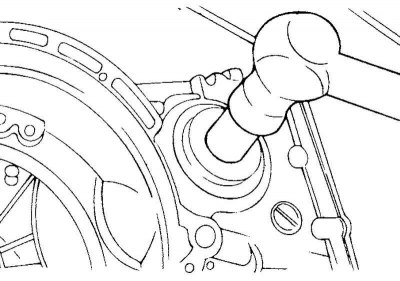
Fig. 3.82. Pressing in the oil seal
Using a special tool (mandrel 09431-21200), install the new oil seal into the gearbox using light blows (Fig. 3.82).
Apply automatic transmission fluid (ATF) to the working lip of the oil seal.
Replacing the speedometer drive cable
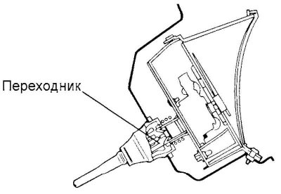
Fig. 3.83. Speedometer drive cable adapter
Correctly install the adapter into the instrument cluster and tie the new speedometer drive cable to it (Fig. 3.83).
Install the rubber bushing so that the cable and the protruding part of the bushing are horizontal.
Caution! The speedometer drive cable must be routed so that the cable bend radius is 150 mm or greater.
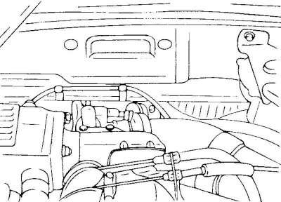
Fig. 3.84. Installing the speedometer drive cable
From the gearbox side, it is necessary to insert the end of the speedometer drive cable into the gearbox and securely tighten the fastening nut (Fig. 3.84).
Caution! If the speedometer cable is not connected correctly or securely, the speedometer reading will be incorrect and abnormal noise will occur. Make sure the speedometer cable is connected correctly.