
Note: The mechanical systems can be checked using the table "Checking the mechanical systems of automatic transmissions".
Checking the torque converter on a fully braked vehicle (stall test)
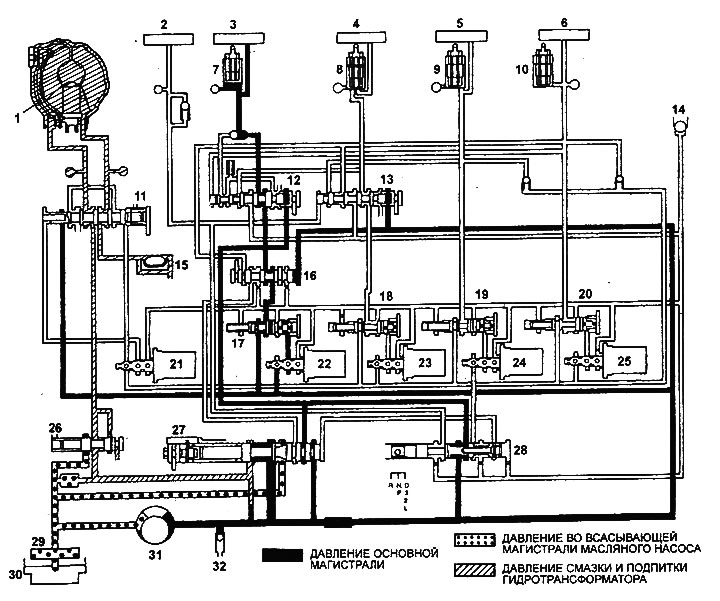
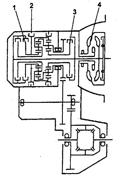
Hydraulic diagram of the automatic transmission control system (selector lever in position "N" or "P").
1 - torque converter lock-up clutch, 2 - reverse clutch, 3 - first gear and reverse brake, 4 - second gear brake, 5 - downshift clutch, 6 - upshift clutch, 7, 8, 9, 10 - hydraulic accumulator, 11 - torque converter lock-up clutch control valve, 12 - emergency mode valve "A", 13 - emergency mode valve "B", 14 - ball valve, 15 - automatic transmission fluid cooler, 16 - changeover valve, 17 - first gear and reverse clutch line pressure regulating valve, 18 - second gear brake line pressure regulating valve, 19 - downshift clutch line pressure regulating valve, 20 - upshift clutch line pressure regulating valve, 21 - torque converter lock-up clutch control electromagnetic valve, 22 - electromagnetic first gear and reverse gear brake control valve, 23 - second gear brake control electromagnetic valve, 24 - clutch electromagnetic valve?; control of the downshift clutch, 25 - electromagnetic valve for controlling the upshift clutch, 26 - pressure regulating valve in the torque converter, 27 - pressure regulator, 28 - range selection valve, 29 - automatic transmission fluid filter, 30 - automatic transmission pan, 31 - automatic transmission pump, 32 - safety valve.
Table. Checking mechanical systems of automatic transmission.
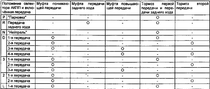
Table. Checking the pressure in the automatic transmission control hydraulic system.
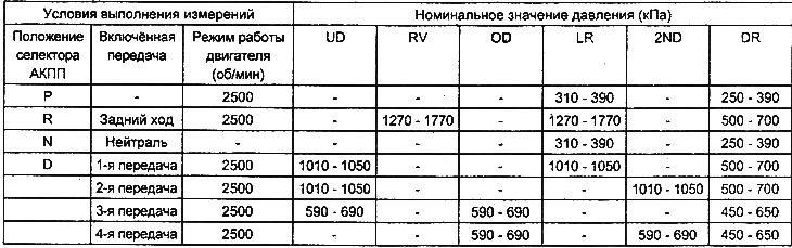
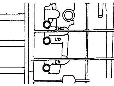
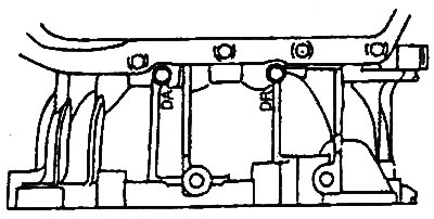
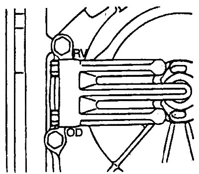
Note: UD - underdrive clutch pressure, RV - reverse clutch pressure, OD - overdrive clutch pressure, LR - first and reverse brake pressure, 2ND - second brake pressure, DR - torque converter lock-up clutch release pressure.
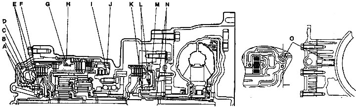
Location of automatic transmission seals.
1. Conduct a check.
Note: The purpose of this test is to measure the maximum engine crankshaft speed with the automatic transmission output shaft fully braked in the "D" and "R" ranges. The value of this speed can be used to determine the operability of the torque converter stator overrunning clutch, as well as the presence of slippage of the friction clutches and brakes of the automatic transmission.
Caution: Do not allow anyone to be in front or behind the vehicle during this test.
- a) Make sure that the verification conditions are met.
Verification conditions:
- Automatic transmission fluid level: at the "NOT" mark on the dipstick
- Temperature of the working fluid in the automatic transmission: 80-100°C
- Engine coolant temperature: 80-100°C
- b) Place brake chocks under the rear wheels of the vehicle.
- c) Raise the parking brake lever fully and depress the brake pedal all the way.
- d) Start the engine.
- d) Set the automatic transmission selector lever to position "D", press the accelerator pedal all the way down and determine the engine crankshaft speed.
- Nominal value: 2000-2900 rpm
Attention:
- Do not hold the throttle fully open for more than 8 seconds during this test.
- If this test needs to be performed more than once, after each test, move the automatic transmission selector lever to the "N" position and let the engine run at 1000 rpm for 2 minutes to cool the working fluid in the automatic transmission between tests.
- Move the selector lever to the "R" position and repeat the check.
2. Analyze the test results.
- a) If the engine crankshaft speed on a fully braked vehicle in the "D" and "R" ranges is greater than the nominal value, the cause may be either low pressure in the hydraulic control system or slippage of the first gear and reverse gear brake.
- b) If the engine crankshaft speed on a fully braked vehicle is higher than the nominal value only in the "D" range, then the reason for this may be slippage of the downshift clutch.
- c) If the engine crankshaft speed on a fully braked vehicle only in the "R" range is greater than the nominal value, then the cause of this may be slippage of the reverse clutch.
- d) If the engine crankshaft speed on a fully braked vehicle in the "O" and "R" ranges is less than the nominal value, then the cause is either a faulty torque converter or insufficient (inappropriate) engine output power.
Note: Check for misfires, ignition timing, etc. If no faults are found in any of the above points, then the torque converter is faulty.
Automatic transmission components.
1 - reverse clutch, 2 - first gear and reverse gear brake, 3 - downshift clutch, 4 - torque converter.
Hydraulic test
1. Measure the pressure in the line.
- a) Warm up the engine so that the automatic transmission fluid warms up to a temperature of 70-80°C.
- b) Raise the vehicle on a lift until the drive wheels are suspended.
- c) Unscrew the service plug of the gearbox housing and connect a pressure gauge in its place.
- Tightening torque of the service plug: 8-10 Nm
- d) Measure the pressure of the working fluid in the line and check that the obtained values correspond to the nominal ones (see the table "Checking the pressure in the automatic transmission control hydraulic system".
 |
 |
- d) After checking, tighten the service plug.
- e) Take measurements by connecting the pressure gauge in series to the ports marked: UD, RV, OD, LR, 2ND and DR.
- g) If the obtained values do not correspond to the technical data, then determine the cause and location of the malfunction. After eliminating the malfunction, repeat the test.
2. Analyze the test results.
- a) High pressure in all lines (UD, RV, OD, LR, 2ND, DR) may be caused by:
- incorrect adjustment of the automatic transmission control cable;
- pressure regulator malfunction.
- b) Low pressure in all lines (UD, RV, OD, LR, 2ND, DR) may be caused by:
- incorrect adjustment of the automatic transmission control cable;
- automatic transmission pump malfunction;
- clogging of the internal or external filter of the automatic transmission working fluid;
- pressure regulator malfunction;
- safety valve malfunction;
- incorrect installation of the solenoid valve block.
- c) Incorrect pressure only in the "R" range can be caused by:
- pressure regulator malfunction;
- clogging of the channel;
- incorrect installation of the solenoid valve block.
- d) Inadequate pressure only in 3rd or 4th gear may be caused by:
- pressure regulator malfunction;
- clogging of the channel;
- incorrect installation of the solenoid valve block;
- malfunction of the electromagnetic valve controlling the overdrive clutch;
- malfunction of the pressure control valve in the overdrive clutch line;
- malfunction of the switching valve.
- d) Inadequate pressure only in the downshift clutch line may be caused by:
- malfunction of the "K" seal, "L" seal or "M" seal;
- malfunction of the electromagnetic valve controlling the downshift clutch;
- malfunction of the pressure control valve in the downshift clutch line;
- ball valve malfunction;
- clogging of the channel;
- incorrect installation of the solenoid valve block.
- e) Inadequate pressure only in the reverse clutch line may be caused by:
- malfunction of seal "A", seal "B" or seal "C";
- clogging of the channel;
- incorrect installation of the solenoid valve block.
- g) Inadequate pressure only in the overdrive clutch line may be caused by:
- malfunction of the "D" seal, "E" seal or "F" seal;
- malfunction of the electromagnetic valve controlling the overdrive clutch;
- malfunction of the pressure control valve in the overdrive clutch line;
- ball valve malfunction;
- clogging of the channel;
- incorrect installation of the solenoid valve block.
- c) The discrepancy between the pressure in the brake line of the first gear and the reverse gear only can be caused by:
- malfunction of the "I" seal or the "J" seal;
- malfunction of the electromagnetic valve controlling the brake of the first gear and reverse gear;
- malfunction of the pressure control valve in the brake line of the first gear and reverse gear;
- defective switching valve;
- malfunction of the valve "A" of the emergency mode of operation;
- ball valve malfunction;
- clogging of the channel;
- incorrect installation of the solenoid valve block.
- i) Pressure discrepancy only in the second gear brake line may be caused by:
- malfunction of the "G" seal, "H" seal, "O" seal;
- malfunction of the electromagnetic valve controlling the second gear brake;
- malfunction of the pressure control valve in the second gear brake line;
- malfunction of the valve "B" of the emergency mode of operation;
- clogging of the channel;
- incorrect installation of the solenoid valve block.
- k) Inadequate pressure only in the reverse clutch line may be caused by:
- automatic transmission oil cooler malfunction;
- malfunction of the seal "N";
- malfunction of the electromagnetic valve controlling the lock-up clutch of the torque converter;
- malfunction of the torque converter lock-up clutch control valve;
- faulty torque converter pressure control valve;
- clogging of the channel;
- incorrect installation of the solenoid valve block.
- l) The working pressure in the line of the switched-off control element may be caused by:
- incorrect adjustment of the automatic transmission control cable;
- range selection valve malfunction;
- ball valve malfunction;
- incorrect installation of the solenoid valve block.
Road test
1. Turn the ignition key to the "ON" position and check the serviceability of the automatic transmission control relay (presence of battery voltage).
2. With the engine not running, move the automatic transmission selector to position "P" and do the following:
- a) Move the automatic transmission selector sequentially to positions "P", "R", "N", "O", "2", "L". Check the serviceability of the start inhibit switch.
- b) Check the throttle position sensor for proper operation. Measure the voltage at the sensor terminals.
Nominal voltage:
- with accelerator pedal released: 400-1000 mV
- when the accelerator pedal is not fully pressed: increases from 400 mV
- with the accelerator pedal pressed: 4500-5000 mV
- c) Check the serviceability of the brake light switch with the brake pedal pressed and released.
3. Turn the ignition key to the "START" position. Move the automatic transmission selector to the "P" or "N" position, and make sure that starting the engine (cranking the crankshaft with the starter) is possible only in the specified selector positions.
4. Drive the car for 15 minutes or more and check the serviceability of the automatic transmission fluid temperature sensor (the temperature gradually increases to 70-90°C).
5. With the engine idling, move the automatic transmission selector to the "N" position and do the following:
- a) By turning the air conditioner "ON" and "OFF", check the serviceability of the triple switch for refrigerant pressure.
- b) Make sure that the throttle valve is in the fully closed position with the accelerator pedal released and not fully depressed.
- c) Check the crankshaft position sensor with the accelerator pedal released and not fully depressed.
- Sensor readings: 650-900 rpm
- d) Check the connection with the electronic engine control unit with the pedal released and not fully pressed.
- d) After moving the selector from position to position and from position to position, make sure that there are no malfunctions (sharp jolts) when starting to move and delays (more than two seconds) in gear shifting.
6. While driving on a straight horizontal section of the road, move the automatic transmission selector to position "D" and check that the gears being engaged correspond to the specified speed for 10 seconds.
- a) The engine is idling - the automatic transmission selector is in position "L" - the car is stationary.
- b) Automatic transmission selector in position "L" - the car moves at a constant speed of 10 km/h.
- c) Automatic transmission selector in position "2" - the car moves at a constant speed of 30 km/h.
- d) Automatic transmission selector in position "3" - the car moves at a constant speed of 50 km/h.
- d) Automatic transmission selector in position "D" - the car moves at a constant speed of 50 km/h.
7. For the conditions of subparagraphs "a" and "g" of paragraph "6", check the serviceability of the vehicle speed sensor.
8. For the conditions of subparagraph "g" of paragraph "6", check the serviceability of the gearbox input shaft speed sensor (1800-2100 rpm) and the gearbox output shaft speed sensor (1800-2100 rpm).
9. While driving on a straight horizontal section of the road, move the automatic transmission selector to position "D" and check the gear shifting.
- a) Accelerate the car until the automatic transmission shifts to fourth gear with the throttle valve opened by 30% (throttle position sensor voltage 1.5 V).
- b) Brake smoothly until the car stops.
- c) Accelerate the car until the automatic transmission shifts to fourth gear when the throttle valve is opened by 50% (the throttle position sensor voltage is 2.5 V).
Note: Make sure there are no sudden jolts during the checks described in subparagraphs "a" - "c".
- d) When driving in fourth gear at a speed of 40 km/h, shift to third gear.
- d) When driving in third gear at a speed of 30 km/h, shift to second gear.
- e) When driving in second gear at a speed of 20 km/h, shift to first gear.
Note: Make sure that the transmission immediately shifts to a lower gear after moving the automatic transmission selector during the checks described in subparagraphs "d" - "e".
10. Move the automatic transmission selector lever from the "N" position to the "R" position and check that the reverse gear is engaged. While driving on a straight horizontal section of the road at a speed of 10 km/h, make sure that the ratio between the values of the signals from the input shaft speed sensor of the transmission and the output shaft speed sensor of the transmission is equal to the gear ratio with the reverse gear engaged.