
Caution: The throttle position sensor testing procedure is provided in the Fuel Injection (MFI) System chapter.
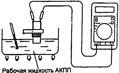
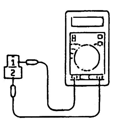
1. Checking the automatic transmission fluid temperature sensor.
- a) Remove the automatic transmission fluid temperature sensor.
- b) Measure the resistance between terminals "1" and "2" of the sensor connector.
| Automatic transmission fluid temperature | Resistance |
| 0°C | 16.7-20.5 kOhm |
| 100°C | 0.57-0.69 kOhm |
- c) Install the automatic transmission fluid temperature sensor and tighten the bolt.
- Tightening torque: 10-12 Nm
2. Check the vehicle speed sensor.
- a) Remove the vehicle speed sensor and connect a 3-10 kOhm resistor to it, as shown in the figure.
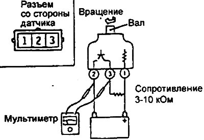
- b) Rotate the vehicle speed sensor shaft and make sure that voltage appears at terminals "2" - "3" of the sensor connector (4 pulses per revolution).
- c) Install the vehicle speed sensor.
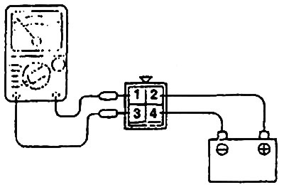
3. Checking the automatic transmission control relay.
- a) Remove the automatic transmission control relay.
- b) Check that there is no short circuit between terminals "1" and "3" of the control relay when power is not supplied.
- c) Using wires with an alligator clip connector, connect terminal "2" of the automatic transmission control relay to the positive terminal of the battery, and terminal "4" to the negative terminal.
- d) Check for a closed circuit between terminals "1" and "3" of the control relay when power is supplied to the relay (with wires connected to the battery terminals).
- d) If the relay operation differs from that described, replace the automatic transmission control relay.
4. Checking the engine start prohibition switch.
- a) Disconnect the engine start inhibit switch connector.
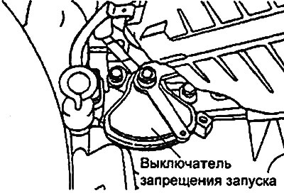
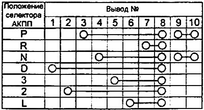
- b) Check the condition of the circuit between the connector terminals at different switch positions according to the table provided.
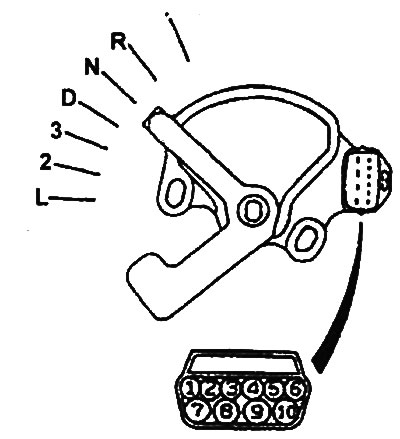
Table. Checking the switch.
1. Checking the resistance of the automatic transmission electromagnetic valves.
- a) Remove the solenoid valve housing cover.
- b) Disconnect the solenoid valve connectors.
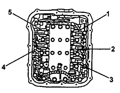
Solenoid valves.
1 - electromagnetic valve for controlling the downshift clutch, 2 - electromagnetic valve for controlling the second gear brake, 3 - electromagnetic valve for controlling the torque converter lock-up clutch, 4 - electromagnetic valve for controlling the first gear brake and reverse gear, 5 - electromagnetic valve for controlling the upshift clutch.
- c) Measure the resistance between terminals "1" and "2" of each solenoid valve.
- Nominal value: 2.7-3.4 Ohm (at 20°C)
- d) If the resistance is outside the nominal value, replace the solenoid valve.
- d) Install the solenoid valve housing cover, having first applied sealant to the mating surface, and tighten the bolts.
- Tightening torque of cover mounting bolts: 8-10 Nm
- Sealant: Hyundai genuine sealant TV1281B or similar