
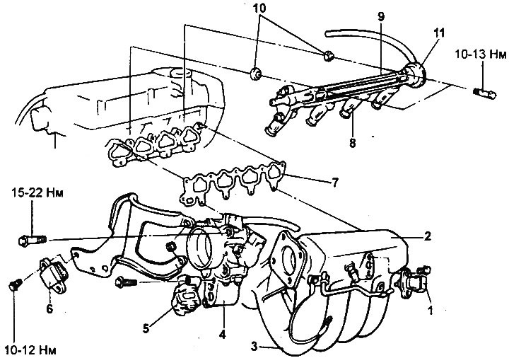
Intake manifold (2.0L/2.4L engines).
1 - absolute pressure sensor in the intake manifold, 2 - intake manifold receiver, 3 - intake manifold, 4 - throttle body, 5 - idle speed control servo drive, 6 - power transistor, 7 - gasket, 8 - injector, 9 - fuel manifold, 10 - sealing gasket, 11 - fuel pressure regulator.
Removal
1. Disconnect the air intake hose from the throttle body.
2. Disconnect the accelerator pedal cable.
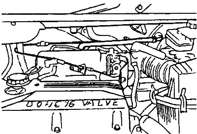
3. Disconnect the coolant hose from the throttle body.
4. Disconnect the positive crankcase ventilation hose and the brake booster vacuum hose.
5. Disconnect the vacuum hoses.
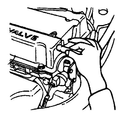
6. Remove the protective cover of the injectors.
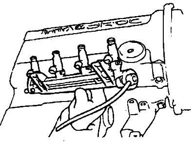
7. Before disconnecting the high-pressure fuel hose from the fuel rail, release any residual pressure from the high-pressure fuel lines to prevent fuel from splashing.
8. Disconnect the fuel injector wiring harness connector.
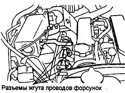
9. Remove the fuel manifold together with the injectors.
Note: Be careful not to drop the injectors when removing the fuel rail.
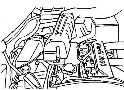
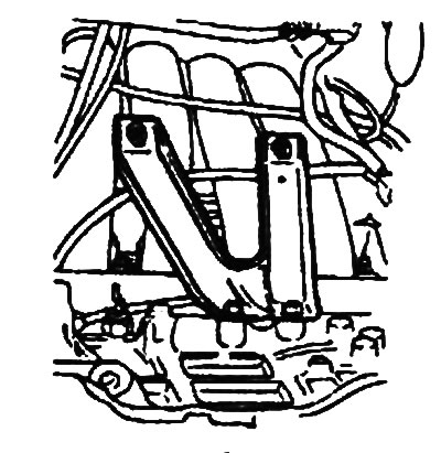
10. Unscrew the intake manifold bracket.
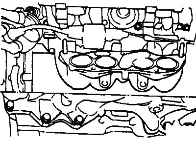
11. Remove the intake manifold.
Installation
1. Replace the intake manifold gasket with a new one and install the intake manifold in place.
Tightening torque:
- bolts: 15-20 Nm
- nuts: 30-42 Nm
2. Install the fuel manifold together with the injectors onto the intake manifold.
Caution: Be careful not to allow the injectors to come into contact (impact) with the edges of the injector holes in the intake manifold.
3. Install the intake manifold support bracket.
4. Connect the fuel injector wiring harness connector. Install the injector protective cover.
5. Connect the high pressure fuel hose.
6. Connect the vacuum hoses.
7. Connect the positive crankcase ventilation hose and the brake booster vacuum hose.
8. Connect the air intake hose to the throttle body.
9. Connect the accelerator pedal cable.
Examination
1. Check all parts, including air hoses, for damage, cracks and deformation, if any are found, replace the part. Clean the parts if necessary.
Caution: When cleaning, do not allow foreign particles to enter the engine cooling jacket channel openings or oil system channels.
2. Check the condition of the intake manifold gasket.
3. Check for blockages in the vacuum outlet fittings, coolant passage channels, and forced crankcase ventilation system channels.
4. Using a straightedge and a set of feeler gauges, measure the non-flatness of the cylinder head mating surface, as well as the mating surfaces of the receiver and intake manifold.
Non-flatness of the mating surface:
- Nominal: less than 0.15 mm
- Maximum allowable: 0.20 mm