Contents: Removal and installation the…⇓ Removal the pressure plate and…⇓ Installing the pressure plate and…⇓ Removal and installation the…⇓ Checking the gap in the…⇓
Removal and installation the compressor
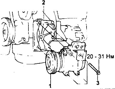
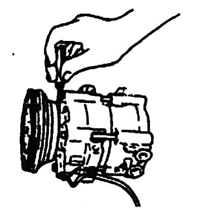
Removing the compressor.
1 - compressor, 2 - compressor mounting bracket (engines G4JP and G4JS), 3 - bolt.
1. Remove the battery and battery tray.
2. Remove the cooling fan diffuser.
3. Pump the refrigerant out of the system.
4. Loosen the compressor drive belt tensioner roller.
5. Disconnect the high pressure hose.
6. Remove the compressor.
7. Installation is carried out in the reverse order of removal.
8. When installing the parts, pay attention to the compressor installation operation.
If a new compressor is installed, first adjust the oil volume as described below, and then install the compressor (i.e. maintain the oil balance in the air conditioning system).
- a) Measure the amount of oil [X ml] that was in the removed compressor.
- b) Drain the amount of oil [Y ml] from the new compressor calculated using the formula below, and then install the new compressor in place.
- Oil volume in a new compressor: 150 ml - X ml - Y ml
Note: [Y ml] refers to the amount of oil remaining in the pipes, condenser, evaporator, hoses, etc.
Amount of oil to add when replacing components:
- Evaporator: 30 ml
- Condenser: 40 ml
- Receiver-dryer: 20 ml
- Compressor: 50 ml
- Tube or hose: 10 ml
Attention:
- Compressor oil must not contain moisture, contaminants, particles, metals, etc.
- Do not mix compressor oils of different grades.
- Compressor oil is very hygroscopic, so do not leave the container with oil open for a long time (i.e. longer than
- this is necessary for filling). Close the container immediately after use.
Removal the pressure plate and clutch rotor
1. Loosen the pressure plate mounting bolt using a wrench and a special tool.

2. Remove the pressure plate and adjusting washer from the compressor shaft. If the pressure plate cannot be removed by hand, tighten the bolt (M8) into the central hole of the plate so that the plate is disconnected and can be removed.
3. Remove the clutch rotor retaining ring.
4. Remove the clutch rotor assembly with the bearing from the compressor.
Installing the pressure plate and clutch rotor
1. Clean the bearing seat of the clutch rotor on the compressor shaft, remove traces of dirt and rust.
2. Install the clutch rotor assembly with the bearing on the compressor shaft.
3. Install the clutch rotor retaining ring with the chamfered side facing out.
4. Place an adjusting washer of the appropriate thickness on the splines of the pressure plate on the compressor side and smoothly slide the plate onto the compressor shaft.

5. Install the new pressure plate mounting bolt onto the end of the compressor shaft. Tighten the bolt to the specified torque.
- Tightening torque: 10-15 Nm
Caution: Do not use an air tool (impact wrench) when performing this operation.
Removal and installation the electromagnetic clutch winding
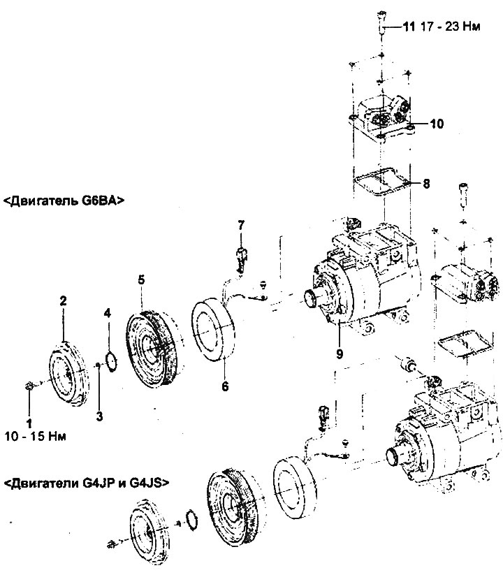
Removing the compressor electromagnetic clutch.
1 - bolt, 2 - pressure plate, 3 - adjusting washer, 4 - retaining ring, 5 - clutch rotor assembly with bearing, 6 - clutch winding, 7 - clutch connector, 8 - gasket, 9 - compressor assembly, 10 - block of fittings, 11 - bolt.
1. Remove the pressure plate and clutch rotor.
2. Install the protective device on the compressor shaft.
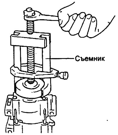
3. Install the pulley onto the compressor shaft. Align the end of the puller bolt with the centering groove of the compressor shaft guard and position the puller tabs around the rear plane of the clutch winding.
4. Remove the coupling winding from the compressor shaft by turning the puller bolt with a wrench.
Caution: Do not use an air tool (impact wrench) when performing this operation.
5. Installation is carried out in the reverse order of removal.
Checking the gap in the electromagnetic clutch
1. Using a flat feeler gauge, measure the air gap between the electromagnetic clutch pressure plate and the contact surface of the clutch rotor.
- Nominal clearance: 0.35-0.65 mm
2. Measure the clearance at three points around the circumference of the compressor clutch rotor.
3. If the measured gap does not correspond to the range of nominal values, then make the necessary gap adjustment by installing an adjusting washer of the appropriate thickness.