
Contents: Checking the temperature controller…⇓ Checking the coolant temperature…⇓ Disassembly and assembly ⇓
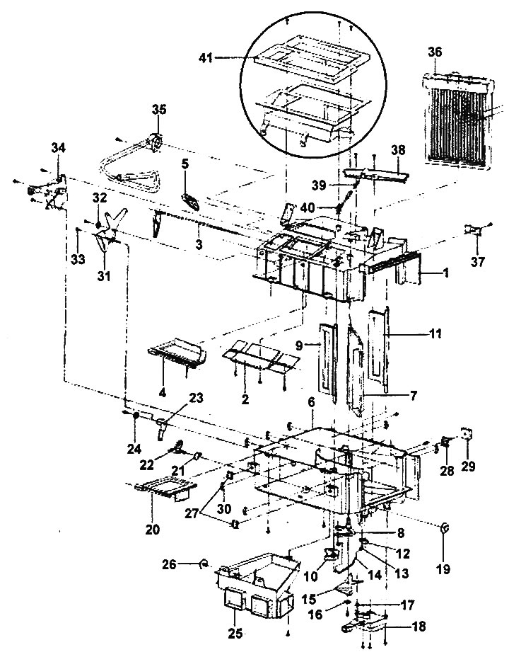
Disassembling the heater.
1 - upper part of heater housing, 2 - ventilation mode flap, 3 - ventilation mode flap lever, 4 - windshield heating flap, 5 - windshield heating flap lever, 6 - lower part of heater housing, 7 - temperature control flap, 8 - temperature control flap lever, 9 - temperature control flap "A", 10 - temperature control flap "A" lever, 11 - bypass flap, 12 - bypass flap lever, 13 - rod holder, 14 - rod, 15 - lever (large) of temperature control flap, 16 - spring washer, 17 - guide sleeve, 18 - temperature control flap servo drive (air conditioning with automatic control), 19 - guide sleeve, 20 - footwell air supply flap, 21 - spring, 22 - footwell air supply flap lever, 23 - footwell air supply flap lever (large), 24 - spring washer, 25 - lower distribution air duct (to the footwell), 26 - guide sleeve, 27 - nut, 28 - bolt with lock, 29 - heater seal "A", 30 - lock, 31 - air flow direction selection flap control cam, 32 - spring washer, 33 - rod holder, 34 - air flow direction selection flap servo drive, 35 - air bypass hose, 36 - heater radiator, 37 - lock, 38 - heater radiator trim, 39 - stopper, 40 - sensor, 41 - central air duct.
Checking the temperature controller servo drive
1. The temperature control servo is installed in the heater unit. Depending on the position of the control switches and the switches on the deflectors (air ducts), the servo will regulate the temperature and air supply to the cabin.
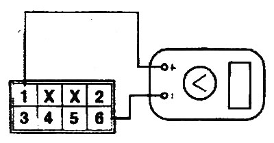
2. Connect a voltmeter to terminals "1" (+) and "6" (-) of the temperature controller servo connector and check the voltage at the connector terminals in accordance with the table.
| Switch position | Voltage |
| COOL (maximum cooling position) | 0.3±0.15 V |
| HOT (maximum heating position) | 4.7±0.15 V |
Checking the coolant temperature sensor in the heater (air conditioning with automatic control)
1. The heater coolant temperature sensor, located in the heater core, measures the temperature of the coolant passing through the heater core. Its signal is used to electronically control the supply of heated air.
2. Checking the sensor.
- a) Immerse the measuring part of the sensor in water.
- b) Measure the resistance between the sensor terminals at the temperature values specified below and make sure that the resistance is within the nominal value.
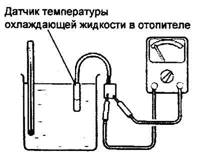
Nominal value:
- at a water temperature of 25°C: 12.5±0.5 kOhm
- at a water temperature of 60°C: 2.5±0.3 kOhm
Disassembly and assembly
1. When removing parts, follow the figure "Disassembling the heater".
2. Installation is carried out in the reverse order of removal.