
Contents: General information ⇓ The principle of operation of the…⇓ Reading fault codes ⇓ Emergency operation mode ⇓ Removal and installation the heater…⇓ Checking the Sunlight Sensor ⇓ Checking the outside air temperature…⇓ Checking the cabin temperature sensor ⇓
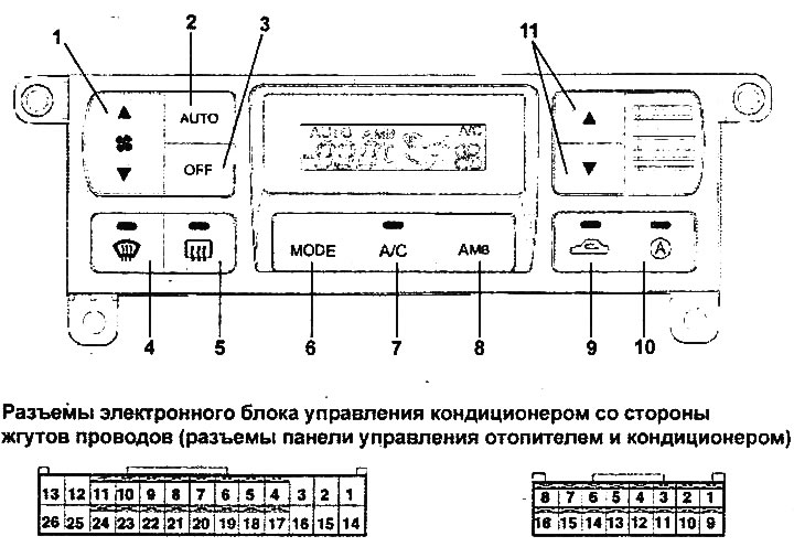
Control panel for air conditioner with automatic control and connectors of the air conditioner control unit.
1 - heater fan mode switch, 2 - automatic control switch, 3 - control system switch, 4 - windshield defroster switch, 5 - rear door glass heater and side rear-view mirror heater switch, 6 - ventilation mode selection switch, 7 - air conditioner switch, 8 - switch for displaying outside air temperature readings, 9 air intake location selection switch, 10 - AQS system switch (models with AQS system), 11 - temperature selection switch.
General information
1. The air conditioner control panel uses touch-sensitive switches. A liquid crystal display is used to display information about the system parameters. A quick or unacceptable change in the system parameters by the user is accompanied by audible buzzer signals. The set parameters and state (position of the flaps, etc.) of the system are saved in the control unit memory after the ignition is turned off.
Note: If the wire was disconnected from the negative terminal of the battery, the system will go to the initial state (to the manufacturer's settings: automatic control mode with a temperature of 25°C).
2. In the automatic mode (AUTO), the required temperature, the rate of its change and the amount of air supplied to the passenger compartment are determined by the value specified by the user and the sensor signals. To maintain the temperature, automatic control is used for the temperature regulator servo drive, the air flow direction selector flap servo drive, the air intake mode selector flap servo drive, the heater fan electric motor and the compressor.
- The permissible range for setting the air temperature in the cabin is 17-32°C (in 0.5°C increments)
Heater electric fan:
- Maximum voltage at "HI" level (AUTO): 10.6 V
- Minimum voltage in automatic mode: 4.5 V
- Minimum voltage in manual control mode: 3.8 V
- Time to switch speed levels from "LO" to "MAX HI": 6 seconds
Note: If the air conditioning system operates in automatic mode (AUTO), the "MIX" position of the air flow direction selector flap is not used and the air flow directions change in the following order: "VENT" → "B/L" → "FLOOR" → "VENT".
3. The functioning of the system components is controlled by a self-diagnostic system.
4. Some models are equipped with an air quality monitoring system (AQS), which detects harmful substances and substances with a strong odor in the air. After the ignition is turned on, the air quality monitoring system will warm up for 34.5±5 seconds. During warming up and if harmful substances are detected (automatic system operation mode), air recirculation is activated.
The principle of operation of the self-diagnostic system
1. The built-in self-diagnosis function of the air conditioning control unit (FATC) detects a malfunction in the electrical circuit and records a malfunction code for the corresponding system component in the control unit memory.
2. If some components fail, the air conditioning system switches to emergency operation mode (instead of incorrect signals, the data set by the manufacturer is used).
Reading fault codes
1. Turn the ignition key to the "ON" position.
2. While holding down the "AUTO" switch, press the "АМВ" switch (switch for displaying outside air temperature readings) more than 4 times within 2 seconds.
3. After the LCD display on the air conditioner control panel flashes 3 times at a frequency of 0.5 seconds, the self-diagnosis process will begin.
4. Pressing the "AUTO" switch will perform another check on the LCD display and display the next diagnostic code (if there is a malfunction). Pressing it again will return the system to its previous state.
5. To exit the code reading mode, press the "OFF" switch.
Note:
- The two-digit number of the corresponding fault code will flash instead of the set air temperature readings at a frequency of 0.5 seconds and will be accompanied by a buzzer signal.
- If there are two or more fault codes, the codes will be displayed sequentially and the number of each code will flash twice on the display.
- If the test is performed in a dark place, the sunlight sensor fault code may appear on the display. Try to move the test to a bright place, if the fault code does not disappear after that, then there may be a fault in the sunlight sensor circuit.
- To view one of the codes, press the "A/C" switch.
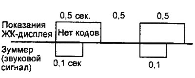
Normal condition. |
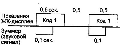
Only one fault code. |
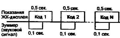
More than two fault codes. |
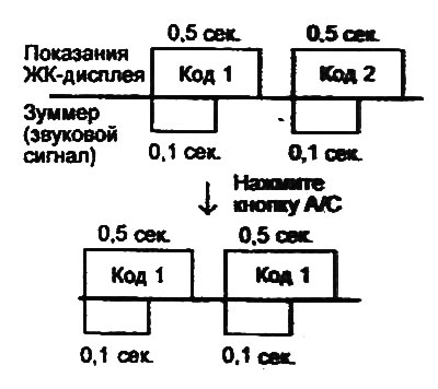 |
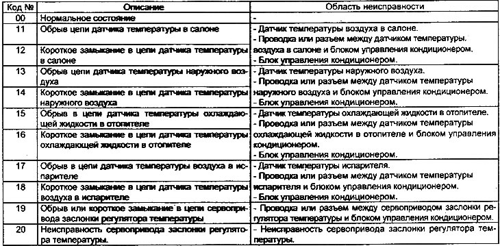
Table of fault codes for air conditioner with automatic control.
Emergency operation mode
1. If the cabin air temperature sensor is faulty (open circuit or short circuit), then the cabin air temperature is taken to be equal to 25°C.
2. If the outside air temperature sensor is faulty (open circuit or short circuit), the outside air temperature is taken to be 20°C.
3. If the evaporator air temperature sensor is faulty (open circuit or short circuit), the evaporator temperature is taken to be -2°C.
4. If the evaporator temperature sensor is faulty (open circuit or short circuit), the windshield heating mode will turn off after 10 minutes.
5. If the temperature controller servo drive is faulty (open circuit or short circuit), then at a temperature of 17°C-24.5°C the maximum cooling mode (MAX COOL) is set, and at a temperature of 25-32°C the maximum heating mode (MAX-HOT) is set.
Removal and installation the heater and air conditioner control panel
The procedures for crushing and installing the heater and air conditioning control panel are given in the "Body" chapter.
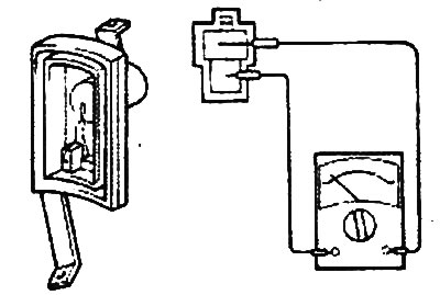
Checking the Sunlight Sensor
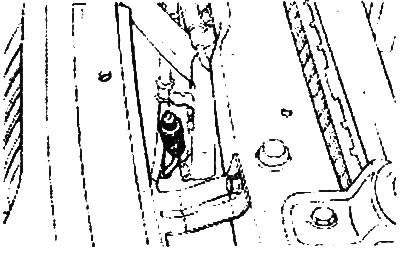
1. The sensor is installed in the center of the instrument panel next to the windshield deflector.
2. The sensor measures the intensity of solar radiation and sends a corresponding signal to the air conditioning control unit. The sensor signal is used to control the rotation speed of the heater electric fan and control the temperature of the air supplied to the passenger compartment.
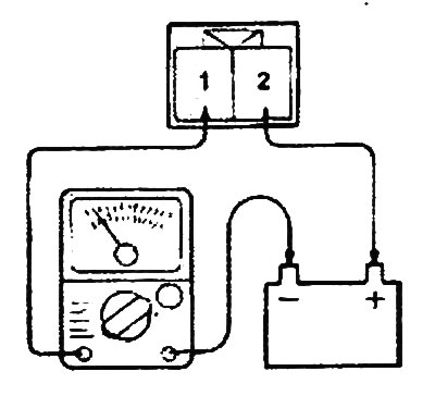
3. Using a portable lamp, change the intensity of illumination of the photocell on the driver and passenger sides. Measure the change in voltage between terminals "1" and "2" of the sensor.
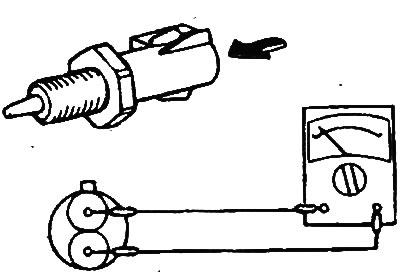
Checking the outside air temperature sensor
1. The sensor is installed in front of the radiator of the engine cooling system. The sensor measures the outside air temperature (outside the cabin) and is a thermistor with a negative temperature coefficient. The resistance of the sensor increases at low temperatures and decreases at high air temperatures.
2. The sensor signal is used to control the temperature of the air supplied to the passenger compartment, the emergency mode of the sensors, control the temperature regulator flap, control the rotation speed of the heater electric fan, control the mixing of air flows and regulate the relative humidity of the air in the passenger compartment.
3. Disconnect the sensor connectors and use an ohmmeter to check that the resistance at a temperature of 20°C corresponds to the nominal value.
- Nominal value: 36.5±2.3 kOhm
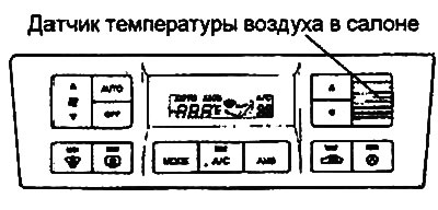
Checking the cabin temperature sensor
1. The sensor detects the air temperature in the passenger compartment. The sensor signal is used to control the temperature of the air supplied to the passenger compartment, the emergency mode of the sensors, control the temperature regulator flap, control the rotation speed of the heater electric fan and automatic control of the air conditioner.
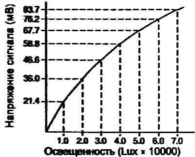
2. The sensor signal should match the graph below.
 |
 |