
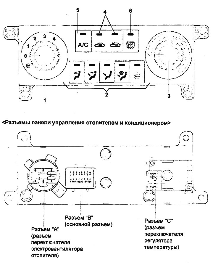
Control panel for manual air conditioner.
1 - heater electric fan switch (electric fan speed control), 2 - air flow direction selection switches (air flow control), 3 - temperature controller switch (air temperature control), 4 - air intake location selection switches, 5 - air conditioner switch, 6 - rear door glass heater and side rear-view mirror heater switch.
General information
The control panel uses a combination of switches with rotary knobs and touch controls.
The air flow through the heater and air conditioner is controlled by a resistor, which, depending on the position of the switch, changes the voltage on the heater fan electric motor.
The air flow direction selection flap, air intake mode selection flap and air flow mixing flap (for the temperature controller) are controlled by servo drives. The position of the air flow direction selection flap servo drive and the air flow mixing flap servo drive is controlled by signals from built-in sensors.
The compressor is controlled by an electronic engine control unit, which, based on a signal from the air conditioner switch (ON/OFF position), switches the compressor electromagnetic clutch relay on and off. The air conditioning system status is monitored using a thermal switch (a sensor-switch for the refrigerant temperature in the evaporator) and a triple switch for the refrigerant pressure in the system.
Removal and installation the heater and air conditioner control panel
The procedures for removing and installing the heater and air conditioner control panel are given in Chapter "Body".
Checking the heater and air conditioner control panel
1. Checking the heater electric fan switch.
- a) Check for conductivity between the terminals of the heater electric fan switch connector, with the switch in different positions.
| Switch position | Conclusions |
| OFF | - |
| 1 (LOW) | 1 ↔ 4 ↔ 5 |
| 2 (ML) | 2 ↔ 4 ↔ 5 |
| 3(MN) | 4 ↔ 5↔ 6 |
| 4 (HIGH) | 3 ↔ 4 ↔ 5 |
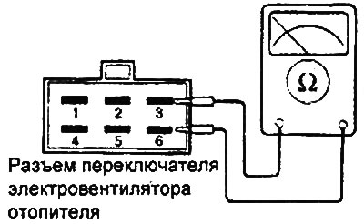
- b) If the circuit condition is not as specified, replace the heater and air conditioner control panel.
2. Checking the air intake location selection switch.
- a) Check for conductivity between the terminals of the air intake location selection switch connector, with the switch in different positions.
| Switch position | Conclusions |
| FRESH | 5 ↔ 9 |
| RECIRCE | 13 ↔ 9 |
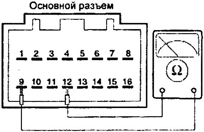
- b) If the circuit condition is not as specified, replace the heater and air conditioner control panel.
3. Checking the temperature controller switch.
The basis of the material is information from the website: HYUNDAIBOOK
- a) Check for conductivity between the terminals of the temperature controller switch connector, with the switch in different positions.
| Switch position | Conclusions |
| VENT | 6 ↔ 9 |
| B/L | 7 ↔ 9 |
| FLOOR | 8 ↔ 9 |
| MIX | 14 ↔ 9 |
| DEFROST | 15 ↔ 9 |
- b) If the circuit condition is not as specified, replace the heater and air conditioner control panel.