Contents: Disassembly and assembly ⇓ Checking the thermal switch…⇓ Checking the evaporator air…⇓ Checking the heater fan motor ⇓ Checking the Heater Fan Motor…⇓ Checking the heater fan motor relay ⇓
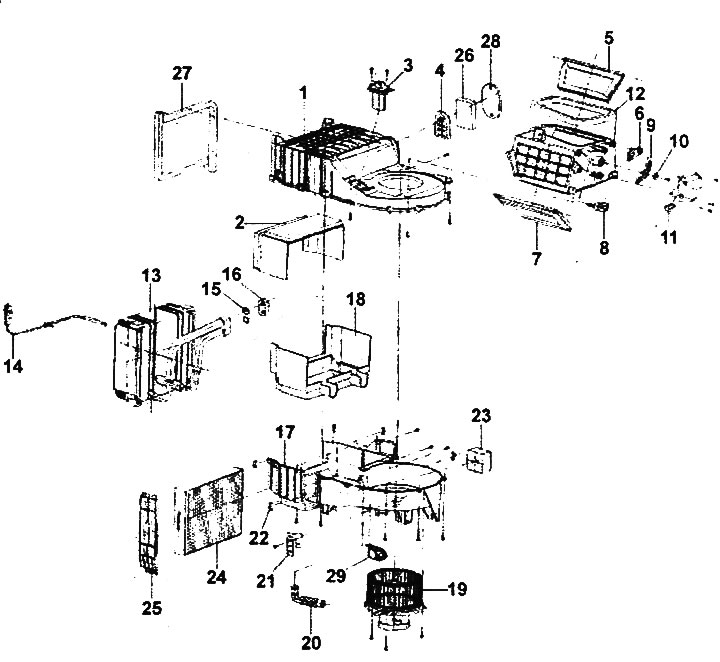
Disassembling the heater electric fan unit.
1 - upper part of the evaporator housing, 2 - upper part of the evaporator casing, 3 - resistor (air conditioner with manual control) or power transistor (air conditioner with automatic control), 4 - evaporator tube mounting bracket, 5 - intake air duct flap, 6 - intake air duct flap lever, 7 - intake air duct flap "A", 8 - intake air duct flap lever "A", 9 - lever (large) of the intake air duct flap, 10 - spring washer, 11 - air intake mode selection flap servo drive, 12 - intake air duct housing seal, 13 - evaporator, 14 - thermal switch (thermistor), 15 - O-ring, 16 - evaporator tube cover, 17 - lower part of the evaporator housing, 18 - lower part of the casing evaporator, 19 - heater fan electric motor and impeller assembly, 20 - heater fan cooling tube, 21 - bracket, 22 - retainer, 23 - seal, 24 - cabin filter, 25 - cabin filter cover, 26 - seal, 27 - seal, 28 - gasket, 29 - power relay (air conditioning with automatic control).
Note: Removal of the cabin filter is described in the chapter "Maintenance and general check and adjustment procedures".
Disassembly and assembly
1. When removing parts, follow the figure "Disassembling the heater electric fan unit".
2. Installation is carried out in the reverse order of removal.
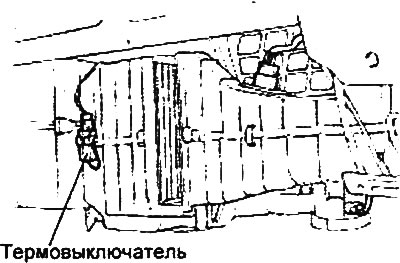
Checking the thermal switch (thermistor)
1. The thermal switch (thermistor) detects the evaporator temperature. The sensor signal switches off the power supply to the compressor electromagnetic clutch relay to prevent the evaporator from freezing due to excessive cooling.
2. Checking the thermal switch.
- a) Remove the glove box.
- b) Start the engine.
- c) Turn on the air conditioner.
- d) Using a multimeter, measure the voltage between terminals "2" and "3" of the thermistor and check its operation.
- Nominal voltage: 12V
Triggering conditions:
- OFF→ON: 4.3 ±1.0°C
- ON→OFF: 1.5±0.5°C
Checking the evaporator air temperature sensor (air conditioner with automatic control)
1. The evaporator air temperature sensor is installed on the evaporator casing.
2. The sensor determines the air temperature in the evaporator and sends a corresponding signal to the air conditioner control unit.
3. Checking the sensor.
- a) Remove the evaporator.
- b) Remove the evaporator air temperature sensor.
- c) Measure the resistance between the sensor terminals at the temperature values specified below and make sure that the resistance matches the nominal value.
Nominal value:
- at an air temperature of 0°C: 11.1-11.6 kOhm
- at an air temperature of 15°C: 5.8-6.1 kOhm
Checking the heater fan motor
1. Connect power (battery voltage) to the motor terminals and check that the fan rotates.
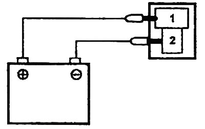
2. Reverse the polarity of the connection and make sure that the electric motor rotates in the opposite direction.
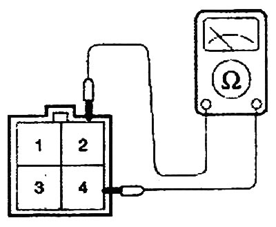
Checking the Heater Fan Motor Resistor (Manual Air Conditioner)
Measure the resistance between the terminals of the resistor connector. If the resistance does not correspond to the nominal values, replace the resistor.
Table. Nominal values.
| Switch position | Chain (terminals) | Resistance, Ohm |
| LO | 4 ↔ 3 | 2,9±5% |
| ML | 4 ↔ 1 | 1,2±0,12% |
| MN | 4 ↔ 2 | 0,4±0,04% |
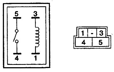
Checking the heater fan motor relay
1. Check for continuity between terminals "1" ↔ "3" when the air conditioner is on.
2. Make sure there is conductivity between terminals "4" ↔ "5" when applying voltage from the battery to terminals "1" and "3".