
With on-board diagnostics (OBD) system
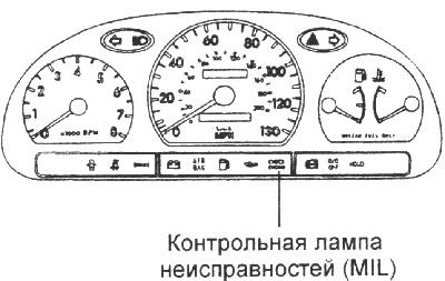
The vehicle's MIL indicator lamp lights up when there are malfunctions in the engine management system. However, the MIL lamp will not light up after three engine starts if the previously detected malfunction no longer occurs. After the ignition is turned on (before the engine is started), the indicator lamp lights up continuously, which indicates the normal operation of the diagnostic system of malfunctions. The indicator lamp with the "OBD" system lights up when malfunctions occur in the following system components:
- catalytic converter;
- fuel system;
- air flow meter;
- manifold absolute pressure sensor;
- engine air temperature sensor;
- coolant temperature sensor;
- throttle position sensor;
- upper oxygen sensor;
- heater of the lower oxygen sensor;
- lower oxygen sensor;
- upper oxygen sensor heater;
- fuel injectors;
- misfires;
- crankshaft angle sensor;
- camshaft position sensor;
- fuel vapor recovery system;
- vehicle speed sensor;
- idle speed control valve;
- electrical power supply;
- ECM;
- malfunction of the gearbox;
- acceleration sensor;
- mIL signal request;
- ignition control unit.
Without on-board diagnostics (OBD)
The MIL comes on when there is a fault in the engine management system. However, the MIL will not come on after three engine starts if the fault that was detected earlier does not occur again. After the ignition is turned on (before the engine is started), the MIL comes on continuously, which indicates that the diagnostic system is working properly.
The control lamp lights up when faults occur in the following system elements:
- heated oxygen sensor;
- manifold absolute pressure sensor;
- throttle position sensor;
- coolant temperature sensor;
- modulator for controlling the engine idle speed;
- fuel injectors;
- ECM.
Examination
1. After turning on the ignition, the indicator lamp lights up for 5 seconds and then goes out.
2. If the indicator lamp does not light, check the electrical circuit of the lamp, the integrity of the fuse and the serviceability of the lamp.
Self-diagnosis
The ECM constantly monitors input and output signals and other signals under certain conditions. When a malfunction is detected, the ECM stores a diagnostic trouble code (DTC) in memory and outputs the code to the diagnostic connector. Diagnostic trouble codes (DTCs) can be read using the MIL or the HI-SCAN scanner. Diagnostic trouble codes (DTCs) remain in memory until the battery cables are disconnected or the connector is disconnected from the ECM, or until they are cleared using the HI-SCAN scanner.
Note: If the connector is disconnected with the ignition on, a DTC will be stored in the memory. In this case, disconnect the negative battery cable for more than 15 seconds, which will erase the diagnostic memory.
1. If the same malfunction occurs and persists for two driving cycles, the MIL lamp will automatically illuminate.
2. The MIL will not illuminate after three engine starts if the previously detected fault no longer occurs.
3. A diagnostic trouble code (DTC) is stored in the ECM memory when a malfunction is detected after two consecutive driving cycles. The MIL illuminates when a malfunction is detected the second time the engine is started.
When a misfire is detected, a malfunction code is stored and the MIL lamp illuminates immediately after the malfunction is detected.
4. The fault code is automatically cleared from the ECM memory if the same fault is not detected within 40 engine starting cycles.
Diagnostic Trouble Codes
With on-board diagnostics (OBD) system
| Code | Malfunction |
| P0030 | Damage to the oxygen sensor heater circuit (group 1, sensor 1) |
| P0031 | Oxygen Sensor Heater Circuit Low (Bank 1 Sensor 1) |
| P0032 | Oxygen Sensor Heater Circuit High (Bank 1 Sensor 1) |
| P0036 | Damage to the oxygen sensor heater circuit (group 1, sensor 2) |
| P0037 | Oxygen Sensor Heater Circuit Low (Bank 1 Sensor 2) |
| P0038 | Oxygen Sensor Heater Circuit High (Bank 1 Sensor 2) |
| P0106 | Absolute air pressure sensor characteristic failure |
| P0107 | Absolute pressure sensor signal level low |
| P0108 | Absolute pressure sensor signal level high |
| P0112 | Low air temperature sensor signal level |
| P0113 | High air temperature sensor signal level |
| Code | Malfunction |
| P0116 | Damage to the electrical circuit of the coolant temperature sensor |
| P0117 | Low signal level of the coolant temperature sensor |
| P0118 | Coolant Temperature Sensor High Signal |
| P0121 | Damage to the electrical circuit of the throttle position sensor |
| P0122 | Throttle Position Sensor Low Signal |
| P0123 | Throttle Position Sensor High Signal |
| P0130 | Damage to the electrical circuit of the oxygen sensor (group 1, sensor 1) |
| P0131 | Low Oxygen Sensor Signal |
| P0132 | High oxygen sensor signal level (group 1, sensor!) |
| P0133 | Slow response of oxygen sensor (group 1, sensor 1) |
| P0134 | Low oxygen sensor efficiency |
| P0136 | Oxygen Sensor Circuit Malfunction (Group 1, Sensor 2) |
| Code | Malfunction |
| P0137 | Heated Oxygen Sensor (HO2S) Low Signal (Bank 1 Sensor 2) |
| P0138 | Heated Oxygen Sensor High Signal (Bank 1 Sensor 2) |
| P0140 | Checking the oxygen sensor measurement range |
| P0171 | Over-lean mixture (group 1) |
| P0172 | Over-enrichment of the mixture (group 1) |
| P0230 | Fuel pump circuit malfunction |
| PG261 | Low level of control signal to injector 1st cylinder |
| P0264 | Low level of control signal to the injector of the 2nd cylinder |
| PQ267 | Low level of control signal to the injector of the 3rd cylinder |
| P0270 | Low level of control signal to the injector of the 4th cylinder |
| P0262 | High level of control signal to injector of the 1st cylinder |
| P0265 | High level of control signal to the injector of the 2nd cylinder |
| P0268 | High level of control signal to the injector of the 3rd cylinder |
| P0271 | High level of control signal to the injector of the 4th cylinder |
| P0300 | Random misfires |
| P0301 | Misfire in cylinder 1 |
| P0302 | Misfire in cylinder 2 |
| P0303 | Misfire in cylinder 3 |
| P03C4 | Misfire in cylinder 4 |
| P0325 | Damage to the electrical circuit of the knock sensor (group 1) |
| P0335 | Crankshaft Position Sensor Circuit Malfunction |
| P0336 | Crankshaft Position Sensor Signal Characteristic Out of Range |
| P0340 | Camshaft Position Sensor Circuit Malfunction |
| P0420 | Reduced efficiency of the main catalytic converter (group 1) |
| P0444 | Open circuit in the purge solenoid valve circuit |
| P0445 | Short circuit in the purge solenoid valve circuit |
| P0501 | Incorrect vehicle speed sensor signal characteristic |
| P0506 | Low engine crankshaft speed at idle |
| P0507 | High engine crankshaft speed at idle |
| P0562 | Low voltage level of the vehicle's on-board network |
| P0563 | High voltage level in the vehicle's electrical system |
| P0605 | ECM Read Only Memory Error |
| P1307 | Acceleration sensor malfunction |
| P1308 | Low Acceleration Sensor Signal |
| Code | Malfunction |
| R1309 | High level of acceleration sensor signal |
| R1505 | Low signal level on winding #1 of the idle speed controller |
| R1506 | High signal level on winding #1 of the idle speed controller |
| R1507 | Low signal level on winding #2 of the idle speed controller |
| R1508 | High signal level on winding #2 of the idle speed controller |
| R1586 | Coding signal chain mismatch |
| R1690 | SMATRA immobilizer malfunction |
| R1691 | Antena immobilizer malfunction |
| R1693 | Immobilizer transponder malfunction |
| R1694 | Engine control unit error |
| R1695 | Electrically erasable read-only memory error |
Without on-board diagnostics (OBD)
| Code | Malfunction |
| P0031 | Oxygen Sensor Heater Circuit Low (Bank 1 Sensor 1) |
| P0032 | Oxygen Sensor Heater Circuit High (Bank 1 Sensor 1) |
| DIGGING | Absolute pressure sensor signal level low |
| P0108 | Absolute pressure sensor signal level high |
| P0112 | Low air temperature sensor signal level |
| P0113 | High air temperature sensor signal level |
| P0116 | Damage to the electrical circuit of the coolant temperature sensor |
| P0117 | Low signal level of the coolant temperature sensor |
| P0118 | Coolant Temperature Sensor High Signal |
| P0121 | Damage to the electrical circuit of the throttle position sensor |
| P0122 | Throttle Position Sensor Low Signal |
| P0123 | Throttle Position Sensor High Signal |
| P0130 | Damage to the electrical circuit of the oxygen sensor (group 1, sensor 1) |
| P0131 | Low Oxygen Sensor Signal |
| P0132 | Oxygen Sensor High Signal (Group 1, Sensor 1) |
| P0133 | Slow response of oxygen sensor (group 1, sensor 1) |
| P0134 | Low oxygen sensor efficiency |
| P0171 | Over-lean mixture (group 1) |
| P0172 | Over-enrichment of the mixture (group 1) |
| P0230 | Fuel pump circuit malfunction |
| P0261 | Low level of control signal to injector of the 1st cylinder |
| Code | Malfunction |
| P0264 | Low level of control signal to the injector of the 2nd cylinder |
| P0267 | Low level of control signal to injector of the 3rd cylinder |
| P0270 | Low level of control signal to the injector of the 4th cylinder |
| P0262 | High level of control signal to injector of 1st cylinder |
| P0265 | High level of control signal to the injector of the 2nd cylinder |
| P0268 | High level of control signal to the injector of the 3rd cylinder |
| P0271 | High level of control signal to the injector of the 4th cylinder |
| P0325 | Damage to the electrical circuit of the knock sensor (group 1) |
| P0335 | Crankshaft Position Sensor Target Malfunction |
| P0336 | Crankshaft Position Sensor Signal Characteristic Out of Range |
| P0340 | Camshaft Position Sensor Circuit Malfunction |
| P0501 | Incorrect vehicle speed sensor signal characteristic |
| Code | Malfunction |
| P0506 | Low engine crankshaft speed at idle |
| P0507 | High engine crankshaft speed at idle |
| P0562 | Low voltage level of the vehicle's on-board network |
| P0563 | High voltage level in the vehicle's electrical system |
| P0605 | ECM Read Only Memory Error |
| R1505 | Low signal level on winding #1 of the idle speed controller |
| R1506 | High signal level on winding #1 of the idle speed controller |
| R1507 | Low signal level on winding #2 of the idle speed controller |
| R1508 | High signal level on winding #2 of the idle speed controller |
| R1586 | Coding signal chain mismatch |
| R1690 | SMATRA immobilizer malfunction |
| R1691 | Antena immobilizer malfunction |
| R1693 | Immobilizer transponder malfunction |
| R1694 | Engine control unit error |
| R1695 | Electrically erasable read-only memory error |