
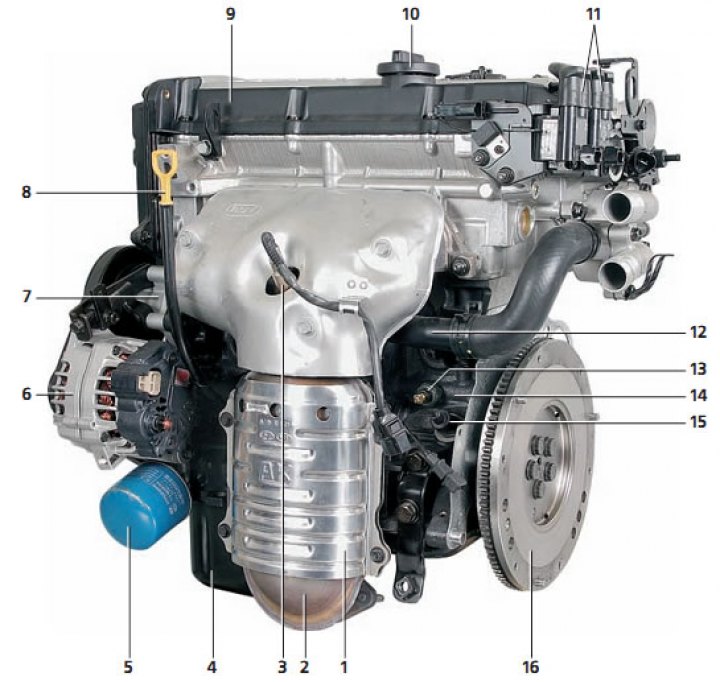
Front view of the engine: 1 - protective screen of the catalytic collector; 2 - catalytic collector; 3 - oxygen concentration sensor; 4 - oil pan; 5 - oil filter; 6 - generator; 7 - coolant pump; 8 - oil level indicator in the engine crankcase; 9 - cylinder head cover; 10 - oil filler cap; 11 - ignition coils; 12 - Cooling system supply pipe; 13 - oil pressure sensor; 14 - cylinder block; 15 - crankshaft position sensor; 16 - flywheel.
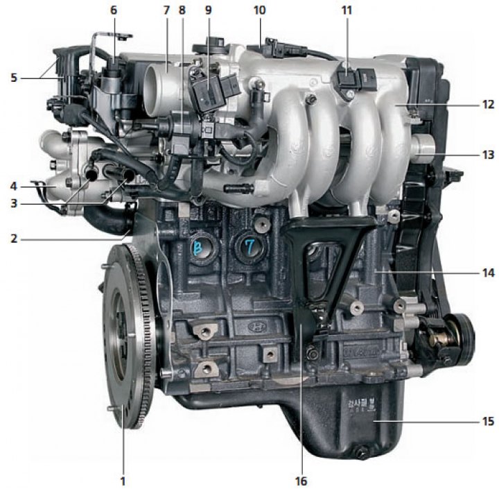
Rear view of the engine: 1 - flywheel; 2 - cooling system supply pipe; 3 - pipes for connection to the heater radiator; 4 - thermostat housing cover; 5 - ignition coils; 6 - camshaft position sensor (phases); 7 - throttle assembly; 8 - electromagnetic valve for purging the adsorber; 9 - throttle position sensor; 10 - idle speed controller; 11 - absolute pressure and air temperature sensor; 12 - inlet manifold; 13 - fuel rail; 14 - cylinder block; 15 - oil pan; 16 - intake manifold bracket.
General information
| Engine type | In-line, with two distribution overhead shafts |
| Number of cylinders | 4 |
| Cylinder diameter, mm | 76,5 |
| Piston stroke, mm: 1.6L engine 1.5L engine | 87,0 83,5 |
| Working volume, cm³ 1.6L engine 1.5L engine | 1599 1495 |
| Compression ratio | 10 |
| Cylinder firing order | 1-3-4-2 |
| Valve timing Inlet valves: opening angle (before TDC), deg closing angle (after BDC), deg Exhaust valves: opening angle (before BDC), deg closing angle (after TDC), deg | 5 35 43 5 |
| Valve overlap angle, deg | 10 |
| Cooling system | Liquid, forced circulation, with electric fan |
| Radiator | Sealed, with a tubular-ribbon core |
| Cooling system capacity, l | 6,5 |
| Water pump | Centrifugal, vane |
| Thermostat | With solid heat sensitive element |
| Air filter | With dry fabric filter element |
| Exhaust system | Expansion-resonance type mufflers; rubber cushion suspension |
Technical data
| Parameter | Nominal size | Maximum permissible size | ||
| Cylinder head | ||||
| Non-flatness of the mating surface, mm, no more than | 0,03 | 0,1 | ||
| Non-flatness of mating surfaces with intake manifold and exhaust manifold, mm, no more than | 0,15 | 0,2 | ||
| Repair size of valve seat sockets, mm: inlet valves: increased by 0.3 mm increased by 0.6 mm exhaust valves: increased by 0.3 mm increased by 0.6 mm | 29,800-29,821 30,100-30,121 27,300-27,321 27,600-27,621 | - - - - | ||
| Repair internal diameter of valve guide bushings, mm: increased by 0.05 mm increased by 0.25 mm increased by 0.50 mm | 11,050-11,068 11,250-11,268 11,500-11,518 | - - - | ||
| Camshafts Height of cams, mm: intake camshaft camshaft of exhaust valves Diameter of shaft bearing journals, mm Clearance between bearing journals and bearing holes, mm Axial clearance, mm | 43,4484 43,8489 27,000 0,035-0,072 0,1-0,2 | 42,94844 3,3489 - - - | ||
| Valves | ||||
| Valve length, mm: intake valves exhaust valves | 91,7 92,3 | - - | ||
| Valve stem diameter, mm: intake valves exhaust valves | 5,955-5,970 5,935-5,950 | - - | ||
| Thickness of the cylindrical part of the valve head, mm: intake valves exhaust valves | 1,1 1,3 | 0,8 1,0 | ||
| Clearance between guide bushings and rods valves, mm: intake valves exhaust valves | 0,03-0,06 0,05-0,08 | 0,10 0,15 | ||
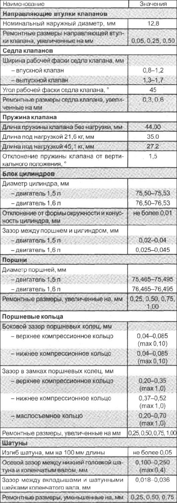
| Valve guide bushings Nominal outside diameter, mm Repair dimensions, mm | 12,8 Increased by 0,05; 0,25; 0,50 | - - | ||
| Valve seats Width of working chamfer of valve seats, mm: intake valves exhaust valves | 0,8-1,2 1,3-1,7 | - - | ||
| Working chamfer angle, deg | 45 | - | ||
| Repair dimensions, mm | Increased by 0.3;0,6 | - | ||
| Valve springs Length, mm: in a free state under load, kgf: 21,6 45,1 Deviation from vertical, deg, no more than | 44,00 35,0 27,2 1,5 | - - - - | ||
| Cylinder block | ||||
| Cylinder diameter, mm: 1.6 l engine 1.5L engine | 76,50-76,53 75,50-75,53 | - - | ||
| Ovality and taper of cylinder mirror, mm, not more than | 0,01 | - | ||
| Clearance between piston and cylinder, mm: 1.6L engine 1.5L engine | 0,025-0,045 0,02-0,04 | |||
| Pistons | ||||
| Piston diameter, mm: 1.6 l engine 1.5L engine Repair dimensions, mm | 76.465-76.495 75.465-75.495 Increased by 0.25; 0,50; 0,75; 1,00 | - - - | ||
| Piston rings Clearance between ring and groove, mm: upper compression ring lower compression ring | 0,04-0,085 0,04-0,085 | 0,1 0,1 | ||
| Gap in the lock, mm: upper compression ring lower compression ring oil scraper ring disc | 0,20-0,35 0,37-0,52 0,20-0,70 | 1,0 1,0 1,0 | ||
| Repair dimensions, mm | Increased by 0.25; 0,50, 0,75; 1,00 | - | ||
| Connecting rods | ||||
| Permissible longitudinal bending, mm, no more than | 0,05 | - | ||
| Misalignment of connecting rod head holes, mm, no more than | 0,1 0, | - | ||
| Axial clearance of the lower connecting rod head on the crankshaft journal, mm | 100-0,250 | 0,4 | ||
| Clearance between bearings and crankshaft journals, mm | 0,018-0,036 | - | ||
| Repair dimensions, mm | Reduced by 0.25; 0,50;0,75 | - | ||
| Crankshaft | ||||
| Diameter of connecting rod journals, mm | 45 | - | ||
| Main journal diameter, mm | 50 | - | ||
| Permissible runout of the middle main journal when supported by the outer journals, mm, no more than | 0,03 | - | ||
| Ovality and taper of main and connecting rod journals, mm, no more than | 0,005 | - | ||
| Crankshaft axial clearance, mm | 0,050-0,175 | - | ||
| Repair dimensions of connecting rod journals, mm: reduced by 0.25 mm reduced by 0.50 mm reduced by 0.75 mm | 44,725-44,740 44,475-44,490 44,225-44,240 | - - - | ||
| Repair dimensions of main journals, mm: reduced by 0.25 mm reduced by 0.50 mm reduced by 0.75 mm | 49,727-49,742 49,477-49,492 49,227-49,242 | - - - | ||
| Flywheel | ||||
| Runout, mm, no more than | 0,1 | 0,13 | ||
| Oil pump | ||||
| Radial clearance between the outer diameter of the driven gear and the bore in the pump body, mm | 0,12-0,18 | - | ||
| Gap between gear teeth, mm | 0,025-0,069 | - | ||
| Clearance between the ends of the gears and the plane of the pump body, mm: pinion gear driven gear | 0,040-0,085 0,06-0,11 | - - | ||
| Oil pressure at idle speed at a temperature of 90-100°C, kPa (kgf/cm²) | 147 (1,5) | - | ||
| Length of the pressure reducing valve spring, mm: in a free state under a load of 6.1 kgf | 46,6 40,1 | - - | ||
| Cooling system | ||||
| Radiator cap Steam valve opening pressure, kPa (kgf/cm²) Air valve opening pressure, kPa (kgf/cm²), no more than | 81,4-108,0 (0,83-1,1) -6,86 (-0,07) | - - - - | ||
| Thermostat Valve opening start temperature,°C Temperature of full valve opening,°C | 82 95 | - - | ||
| Coolant temperature sensor (thermistor type) Resistance: at 20°C, kOhm at 110°C, Ohm | 2,31-2,5 146,9-147,3 | - - | ||
| Name | Meanings |
| Valve timing - inlet valve opening (before TDC), °closing (after BDC),° - exhaust valve opening (before TDC),° closing (after BDC),° |
5 35 43 5 |
| Cylinder head | |
| Deviation from the plane of the mating surface, mm | no more than 0.03 (max 0,1) |
| Deviation from flatness of the mating surface of the collectors, mm | no more than 0.15 (max 0,2) |
| Repair dimensions of the hole for installing the valve seat: — inlet valve, mm increased by 0.3 mm increased by 0.6 mm — exhaust valve, mm increased by 0.3 mm increased by 0.6 mm | 29,800–29,821 27,300–27,321 |
| Name | Meanings |
| Cylinder head | |
| Repair dimensions of the hole for installing the intake and exhaust guide bushing exhaust valves, mm | |
| - increased by 0.50 mm | 11,050–11,068 |
| - increased by 0.05 mm | 11,250–11,268 |
| - increased by 0.25 mm | 11,500–11,518 |
| Camshafts | |
| Height of the kulaik-distributing shaft, mm | |
| — inlet valve - nominal | 43,4484 |
| — maximum permissible | 42,9484 |
| - exhaust valve | |
| — nominal | 43,8489 |
| — maximum permissible | 43,3489 |
| Diameter of the bearing journals of the distribution | 27,000 |
| shaft, mm | |
| Oil clearance in plain bearing | 0,035–0,072 |
| camshaft, mm | |
| Axial clearance of the camshaft, mm | 0,1–0,2 |
| Valves | |
| Valve length, mm | |
| - inlet valve | 91,7 |
| - exhaust valve | 92,3 |
| Valve stem diameter, mm | |
| - inlet valve | 5,955–5,970 |
| - exhaust valve | 5,935–5,950 |
| Working chamfer angle,° | 45 |
| Thickness of the cylindrical part of the head | |
| valves, mm | |
| - inlet valve | 1,1 (min 0,8) |
| - exhaust valve | 1,3 (min 1,0) |
| The gap between the valve stem and the guide | |
| casting sleeve, mm | |
| - inlet valve | 0,03–0,06 (max 0,10) |
| - exhaust valve | 0,05–0,08 (max 0,15) |
| Name | Meanings |
| Crankshaft | |
| Crankshaft journal diameter, mm | 50 |
| Crankshaft connecting rod journal diameter, mm | 45 |
| Bending, mm | no more than 0.03 |
| Deviation from the shape of the circumference of the necks of the | no more than 0.005 |
| belt shaft, mm | |
| Taper of crankshaft journals, mm | no more than 0.005 |
| Crankshaft axial clearance, mm | 0,050–0,175 |
| Repair dimensions of crankpins | |
| of the shaft, mm | |
| -reduced by 0.25 mm | 44,725–44,740 |
| - reduced by 0.50 mm | 44,475–44,490 |
| - reduced by 0.75 mm | 44,225–44,240 |
| Repair dimensions of crankshaft main journals, mm | |
| - reduced by 0.25 mm | 49,727–49,742 |
| - reduced by 0.50 mm | 49,477–49,492 |
| - reduced by 0.75 mm | 49,227–49,242 |
| Flywheel | |
| Runout, mm | no more than 0.1 (max 0,13) |
Tightening torques for threaded connections, Nm
| Front Engine Mount Bracket Fastening Bolt and Nut | 45–55 |
| Engine mount bracket support bolt | 45–55 |
| Oil pressure sensor | 13–15 |
| Cylinder head mounting bolts - 1.6 l engine - 1.5 l engine | 30 + turn 90° further + loosen all bolts + 30 + turn 90° further 35 + turn to an angle of 90° + loosen all bolts + 35 +. turn to an angle of 90° |
| Intake manifold mounting bolts or nuts | 15–20 |
| Exhaust manifold mounting nuts | 25–30 |
| Cylinder head cover mounting bolts | 8–10 |
| Camshaft bearing cap mounting bolts | 12–14 |
| Thrust plate mounting bolt | 32–35 |
| Connecting rod cap mounting bolts | 32–35 |
| Crankshaft main bearing cap fastening bolts | 55–60 |
| Flywheel mounting bolts (with manual transmission) | 120–130 |
| Drive Disc Mounting Bolts (with Automatic Transmission) | 120–130 |
| Crankshaft pulley mounting bolt | 140–150 |
| Camshaft pulley mounting bolt | 80–100 |
| Timing Belt Tensioner Roller Fastening Bolt | 20–27 |
| Timing Belt Guide Roller Fastening Bolt | 43–55 |
| Timing Belt Cover Fastening Bolts | 8–10 |
| Front cylinder block cover mounting bolts | 20–27 |
| Right support mounting nut (large) | 70–95 |
| Right support mounting nut (small) | 35–55 |
| Nuts and bolts securing the right engine support bracket | 35–55 |
| Gearbox support mounting nut | 35–55 |
| Gearbox support to side member mounting bolts | 35–55 |
| Roller support mounting nut | 35–55 |
| Bolt for fastening the roller support bracket to the engine subframe | 70–95 |
| Generator bracket mounting bolt and nut | 20–25 |
| Generator retaining bolt | 12–15 |
| Generator tension bar mounting bolt | 20–27 |
| Air filter housing mounting bolts | 8–10 |
| Resonator mounting bolts | 4–6 |
| Bolts securing the air chamber struts to the cylinder block | 18–25 |
| Throttle body mounting bolts | 15–20 |
| Oxygen sensor to exhaust manifold | 50–60 |
| Nuts securing the exhaust inlet pipe to the exhaust manifold | 30–40 |
| Exhaust Inlet Pipe Bracket Mounting Bolts | 30–40 |
| Bolts securing the exhaust inlet pipe to the catalytic converter | 30–40 |