
Removal
Connecting rod cap
Caution: Keep the connecting rod caps with the corresponding connecting rods for proper reinstallation into the engine cylinders.
1. Unscrew the nuts and remove the connecting rod cap and the lower connecting rod bearing shell. To protect the crankshaft journals, place sections of rubber or plastic tube on the connecting rod cap mounting bolts.
2. Using a wooden block or a hammer handle, push the piston and connecting rod out of the cylinder.
Removal and installation the piston pin
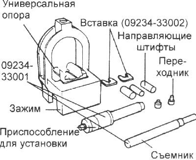
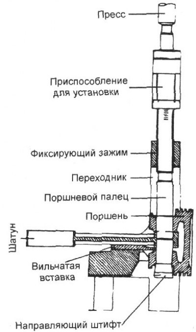
1. Disassembly and assembly of pistons with connecting rods is carried out using devices 09234–33001 and 09234–3302.
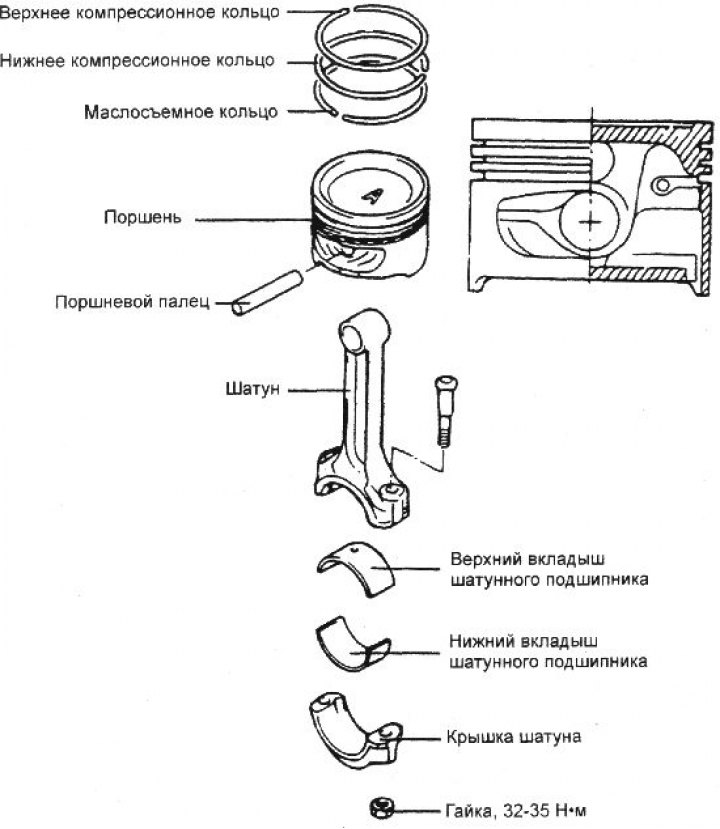
2. The piston pin is pressed into the upper head of the connecting rod and rotates freely in the piston bosses.
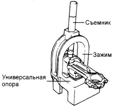
3. The device consists of a clamp with fork inserts, guide pins, adapters, a puller for pressing out and a device for installing the piston pin. When pressing out and pressing in the pin, the piston is installed on the clamp. The guide pins provide the required position of the pin, and the inserts support the connecting rod.
4. To press out the pin, place the piston in the clamp so that the connecting rod rests on the fork inserts. Insert the pressing tool into the hole in the upper part of the clamp and press out the piston pin.
5. To press the pin, install the appropriate fork-shaped inserts on the clamp to support the connecting rod.
6. Insert the connecting rod into the piston. Insert the appropriate guide mandrel into the piston boss and the connecting rod upper head hole. Using light hand blows, move the guide pin so that it enters the other piston boss. Insert the new piston pin into the piston boss from the side opposite the guide pin and install the piston with the connecting rod on the clamp support with the guide pin facing down.
Note: The guide pins determine the position of the connecting rod in the piston. When properly assembled, the guide pin should be positioned directly under the center of the hole in the fixture bracket and should rest evenly on the fork inserts. Using the wrong diameter guide pin will cause the piston and pin to misalign with the support.
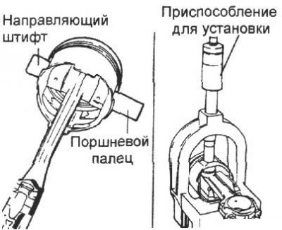
7. Insert the pressing tool through the hole in the clamp arch. Press the piston pin into the connecting rod until the bushing on the shaft contacts the top of the clamp arch, the guide pin should fall out of the piston.
Attention! At the moment when the pressing device reaches the stop in the clamp arch, the pressing force should not exceed 1250±500 kgf.
Examination
Piston and piston pins
1. Check the outside surface of the piston for damage, wear or uneven wear. Replace the piston if necessary.
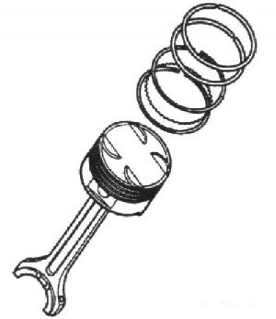
2. Check each piston ring for damage and uneven wear. Replace the piston rings if necessary. When replacing a piston, you must also replace the piston rings.
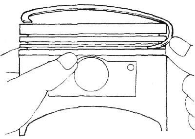
3. Check the piston pin by inserting it into the piston hole. The piston pin should enter the piston smoothly when pressed by hand (at room temperature).
Piston rings
1. Insert a new piston ring into the piston groove and use a feeler gauge to measure the gap between the piston ring and the groove wall. If the gap exceeds the maximum permissible value, replace the piston and rings. If the gap does not exceed the maximum permissible value, replace only the piston rings.
Clearance between piston ring and piston groove, mm:
- upper compression ring: 0.04–0.085
- lower compression ring: 0.04–0.085
Maximum permissible gap: 0.1 mm
2. Measure the piston ring gap by manually inserting the piston ring into the engine cylinder. Use the piston crown to push the piston ring into the bottom of the cylinder. Use a feeler gauge to measure the piston ring gap. If the gap exceeds the maximum permissible value, replace the ring.
Piston ring gap, mm:
- First compression ring: 0.20–0.35
- Second compression ring: 0.37–0.52
- Oil scraper ring: 0.2–0.7
- Maximum clearance: 1.0 mm
When replacing rings without boring the cylinders, the gap in the lock can be checked by installing the rings in the lower, less worn part of the cylinder.
Note: The marking is on the top of the piston ring, on the lock side.
Connecting rods
1. When installing, make sure that the connecting rod and connecting rod cap match the cylinder number they are being installed in. When installing a new connecting rod, make sure that the marks that determine its position are on the same side as the marks on the other connecting rods.
2. Replace the connecting rod if there is damage on both bearing surfaces. Also replace the connecting rod if there is wear or damage on the surface mating with the piston pin.
Piston selection
1. Check the cylinder bore size code located on the face of the cylinder block.
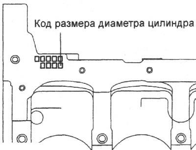
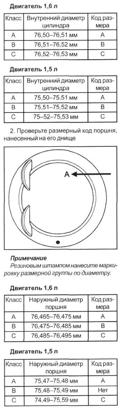
3. Select a piston whose diameter matches the cylinder class. Clearance between piston and cylinder, mm:
- 1.6L engine: 0.025–0.045
- 1.5L engine: 0.020–0.040
Installation
1. Install the oil scraper ring expander.
2. Install the upper side guide of the oil scraper ring. To install the side guide, first place one end of the side guide between the wall of the piston ring groove and the expansion ring, press it, and then, pressing along the perimeter, install it into the piston groove.
Note: Do not use pliers to spread the piston rings when installing the oil scraper ring side guide.
3. Install the lower side guide of the oil scraper ring in the same way.
4. Apply a thin layer of engine oil to the piston and piston rings.
5. Using piston ring pliers, install the lower compression ring.
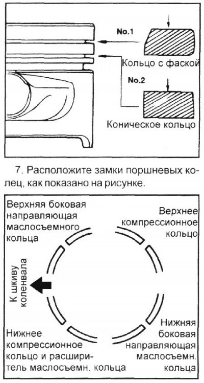
8. Using a special tool, compress the piston rings on the piston. Install the piston with piston rings above the first cylinder.
Using a hammer handle, press the piston into the cylinder until the lower head of the connecting rod is seated on the crankshaft journal.
9. Install the upper main bearing shells onto the engine block. When reinstalling the shells, install them in the same locations they were in before removal.
10. Install the main bearing shells into the crankshaft main bearing caps.
11. Make sure that the marks on the piston and connecting rod are facing the front of the cylinder block.
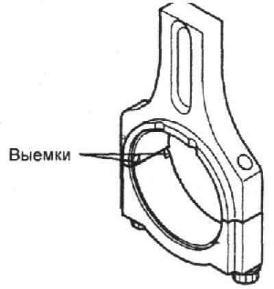
12. When installing a new connecting rod, make sure that the recesses for the bearing shell are on the same side.
13. Tighten the connecting rod cap bolts and nuts.
- 1) Lubricate the threads of nuts and bolts and contact areas with engine oil.
- 2) Tighten the connecting rod cap bolts and nuts to the required torque.
Tightening torque: 32–35 Nm
Warning: Do not reuse connecting rod cap bolts more than three times.
14. Using a feeler gauge inserted between the connecting rod and the crankshaft, measure the connecting rod side clearance.
- Nominal connecting rod side clearance: 0.10 mm
- Maximum clearance: 0.40 mm
15. Install the mesh oil filter.
16. Install the oil pan.
17. Install the cylinder head.