
Contents: Disassembly (75A model) ⇓ Checking the rotor ⇓ Stator check ⇓ Checking the positive terminal of…⇓ Checking the negative terminal of…⇓ Checking three diodes of the…⇓ Replacing brushes ⇓ Disassembly (90A model) ⇓ Checking the rotor ⇓ Stator check ⇓ Checking the positive terminal of…⇓ Checking the negative terminal of…⇓ Checking three diodes of the…⇓ Assembly ⇓ Installation ⇓
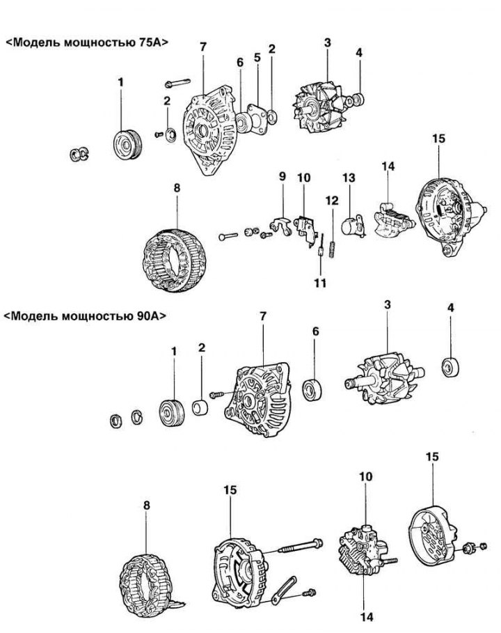
Fig. 7.19. Generator components: 1 – pulley; 2 – sealing ring; 3 – rotor assembly; 4 – rear bearing; 5 – bearing holder; 6 – front generator bracket; 7 – front cover; 8 – stator; 9 – bar; 10 – voltage regulator and brush holder; 11 – brush; 12 – brush spring; 13 – dust protection ring; 14 – rectifier block; 15 – rear generator bracket
Disassembly (75A model)
Loosen the three tie bolts.
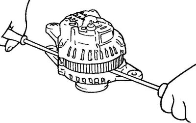
Fig. 7.20. Removing the front generator bracket
Insert a flat-blade screwdriver between the front generator bracket and the stator and, using the screwdriver as a lever, pry (down) the front generator bracket (Fig. 7.20).
Caution: Do not insert the screwdriver too deeply to avoid damaging the stator winding.
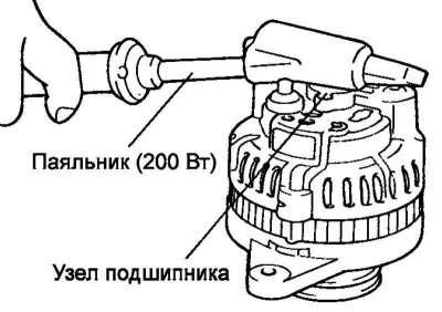
Fig. 7.21. Heating the bearing unit with a soldering iron
You may find it difficult to remove the rear alternator bracket because of the retaining ring used to secure the rear bearing. To make removing the rear bracket easier, heat the bearing assembly with a 200 watt soldering iron (Figure 7.21).
Do not use a heat gun for heating, as this may damage the rectifier diodes.
Clamp the rotor in a vice with the pulley side facing up.
Caution: Be careful not to damage the rotor with the vice jaws.
Loosen the pulley mounting nut, remove the spring washer, then remove the pulley and spacer.
Remove the front generator bracket and two O-rings.
Remove the rotor from the vice.
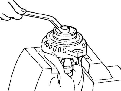
Fig. 7.22. Disconnecting the nut of the generator terminal "B"
Unscrew the screws securing the brush holder and rectifier unit. Then unscrew the nut of the generator terminal "B" (Fig. 7.22).
Remove the stator assembly from the rear bracket.
Remove the dust ring from the brush holder.
Before removing the stator, unsolder the three stator winding wires from the main diodes of the rectifier unit.
Attention! When soldering/unsoldering contacts, be careful that the heat from the soldering iron has as little effect on the diodes as possible. Perform these operations as quickly as possible.
Caution: Be careful not to apply excessive force to the diode contacts.
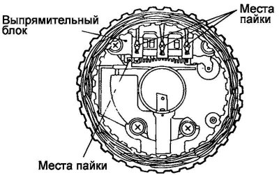
Fig. 7.23. Brush holder contact soldering points
Before disconnecting the rectifier block from the brush holder, unsolder the two contacts soldered to the rectifier block (Fig. 7.23).
Checking the rotor
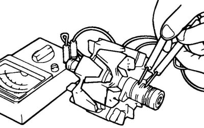
Fig. 7.24. Checking for a closed circuit between the slip rings
Check for a break in the rotor winding. Check for a closed circuit between the slip rings (Fig. 7.24).
If the resistance is too low (tends to 0), this indicates a short circuit. In case of a break in the rotor winding circuit or a short circuit, replace the rotor assembly.
Resistance: approximately 3.1 ohms.
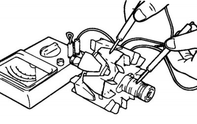
Fig. 7.25. Checking for a short circuit of the rotor winding to ground
Check for short circuit of the rotor winding to ground (Fig. 7.25).
Check for a short circuit between the slip ring and the core. If there is a short circuit (short circuit to ground), replace the rotor assembly.
Stator check
Check for breaks in the stator winding.
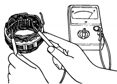
Fig. 7.26. Checking for a closed circuit between the stator winding terminals
Check for a closed circuit between the stator winding terminals. If the winding circuit is open (resistance tends to infinity), replace the stator assembly (Fig. 7.26).
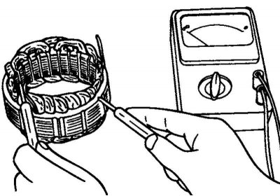
Fig. 7.27. Checking for a short circuit of the winding to ground
Check for a short circuit between the stator winding and the ground (there is no closed circuit between the stator winding and the core) (Fig. 7.27).
If the circuit is closed (resistance tends to zero), replace the stator.
Checking the positive terminal of the rectifier block
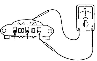
Fig. 7.28. Checking the closed circuit between the terminal of the "positive" diodes of the rectifier unit and the terminal of the stator winding
Using an ohmmeter, make sure that the circuit between the terminal of the "positive" diodes of the rectifier unit and the terminal of the stator winding is closed (the resistance is low). Change the polarity of the ohmmeter probes and measure the resistance (if the resistance is low, i.e. the circuit is closed in both directions, then the diode is broken) (Fig. 7.28).
Replace the rectifier unit assembly.
Checking the negative terminal of the rectifier unit
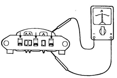
Fig. 7.29. Checking the closed circuit between the terminal of the "negative" diodes of the rectifier unit and the terminal of the stator winding
Using an ohmmeter, make sure that the circuit between the terminal of the "negative" diodes of the rectifier unit and the terminal of the stator winding is closed (the resistance is low). Change the polarity of the ohmmeter probes and measure the resistance (if the resistance is low, i.e. the circuit is closed in both directions, then the diode is broken) (Fig. 7.29).
Replace the rectifier unit assembly.
Checking three diodes of the rectifier block
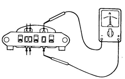
Fig. 7.30. Checking the stator diodes
Test the three diodes by connecting an ohmmeter to both terminals of each diode. For each diode, the circuit should be closed in only one direction (Fig. 7.30).
If there is no closed circuit in both directions (or if there is a closed circuit in both directions), the diode is faulty and the rectifier unit (heat dissipation unit) must be replaced.
Replacing brushes
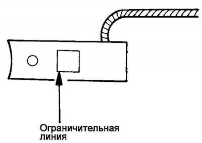
Fig. 7.31. Brush wear limit line
Replace the brushes if their wear has reached the limit line (Fig. 7.31).
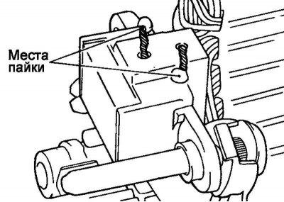
Fig. 7.32. Wire soldering points
Unsolder the brush wire and remove the generator brush with the spring (Fig. 7.32).
Install the spring and new brush into the brush holder.
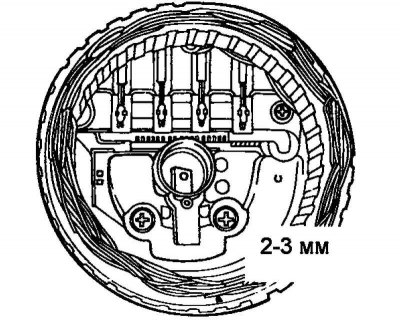
Fig. 7.33. Brush installation diagram
Insert the brush so that there is a distance of 2–3 mm between the edge of the brush holder and the limit line on the brush (Fig. 7.33).
Solder the brush wire to the brush holder
Disassembly (90A model)
Unscrew the nut of the generator terminal "B" and remove the rear cover.
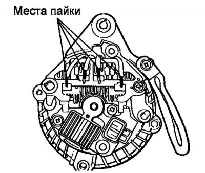
Fig. 7.34. Stator winding wire soldering points
Before removing the stator, unsolder the four stator winding wires from the main diodes of the rectifier unit (Fig. 7.34).
Attention! When soldering/unsoldering contacts, be careful that the heat from the soldering iron has as little effect on the diodes as possible. Perform these operations as quickly as possible.
Caution: Be careful not to apply excessive force to the diode contacts.
Remove the stator assembly from the rear generator bracket.
Remove the brush holder and rectifier block.
Loosen the four tie bolts.
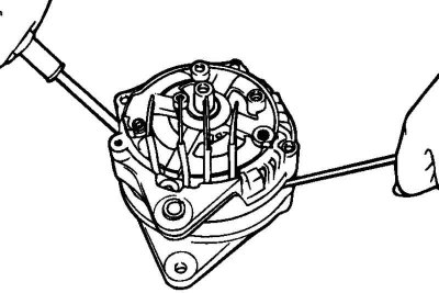
Fig. 7.35. Removing the front generator bracket
Insert a flat-blade screwdriver between the front generator bracket and the stator and, using the screwdriver as a lever, pry (down) the front generator bracket (Fig. 7.35).
Caution: Do not insert the screwdriver too deeply to avoid damaging the stator winding.
Warning! It may be difficult to remove the rear alternator bracket due to the retaining ring used to secure the rear bearing. To aid in removing the rear bracket, heat the bearing assembly with a 200 watt soldering iron.
Warning! Do not use a heat gun for heating, as this may damage the rectifier diodes.
Clamp the rotor in a vice with the pulley side facing up.
Caution: Be careful not to damage the rotor with the vice jaws.
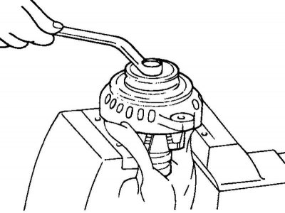
Fig. 7.36. Removing the generator pulley
Unscrew the pulley mounting nut, remove the spring washer, then the pulley and spacer (Fig. 7.36).
Remove the front generator bracket and O-rings.
Remove the rotor from the vice.
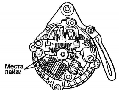
Fig. 7.37. Soldering points of contacts to the rectifier unit
Before disconnecting the rectifier block from the brush holder, unsolder the two contacts (plates) soldered to the rectifier block (Fig. 7.37).
Checking the rotor
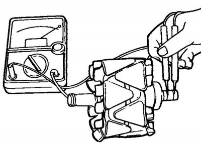
Fig. 7.38. Checking the circuit between the slip rings
Check for a break in the rotor winding. Check for a closed circuit between the slip rings (Fig. 7.38).
If the resistance is too low (tends to 0), this indicates a short circuit. In case of a break in the rotor winding circuit or a short circuit, replace the rotor assembly.
Resistance: approximately 3.1 ohms.
Check for short circuit of the rotor winding to ground.
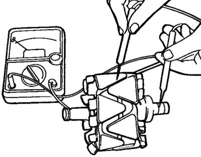
Fig. 7.39. Checking for absence of circuit between the slip ring and the core
Check that there is no closed circuit between the contact ring and the core (Fig. 7.39).
If there is a short circuit (short to ground), replace the rotor assembly.
Stator check
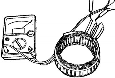
Fig. 7.40. Checking the closed circuit between the stator winding terminals
Check for a break in the stator winding. Check for a closed circuit between the stator winding terminals (Fig. 7.40).
If the winding circuit is open (resistance tends to infinity), then replace the stator assembly.
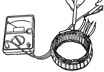
Fig. 7.41. Checking for a short circuit of the stator winding to ground
Check for a short circuit between the stator winding and the ground (there is no closed circuit between the stator winding and the core) (Fig. 7.41).
If the circuit is closed (resistance tends to zero), replace the stator assembly.
Checking the positive terminal of the rectifier block
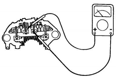
Fig. 7.42. Checking the closed circuit between the terminal of the "positive" diodes of the rectifier unit and the terminal of the stator winding
Using an ohmmeter, make sure that the circuit between the terminal of the "positive" diodes of the rectifier unit and the terminal of the stator winding is closed (the resistance is low) (Fig. 7.42).
Change the polarity of the ohmmeter probes and measure the resistance (if the resistance is low, i.e. the circuit is closed in both directions, then the diode is broken). Replace the rectifier unit as a whole.
Checking the negative terminal of the rectifier unit
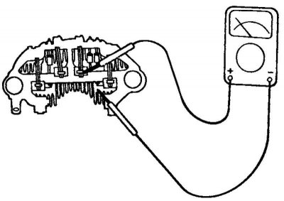
Fig. 7.43. Checking the negative terminal of the rectifier unit
Using an ohmmeter, make sure that the circuit between the terminal of the "negative" diodes of the rectifier unit and the terminal of the stator winding is closed (low resistance) (Fig. 7.43).
Change the polarity of the ohmmeter probes and measure the resistance (if the resistance is low, i.e. the circuit is closed in both directions, then the diode is broken). Replace the rectifier unit as a whole.
Checking three diodes of the rectifier block
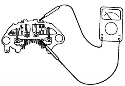
Fig. 7.44. Checking three diodes of the rectifier block
Test the three diodes by connecting an ohmmeter to both terminals of each diode. For each diode, the circuit should be closed in only one direction (Fig. 7.44).
If there is no closed circuit in both directions (or if there is a closed circuit in both directions), the diode is faulty and the rectifier unit (heat dissipation unit) must be replaced.
Assembly
Assembly is carried out in the reverse order of disassembly. Please note the following:
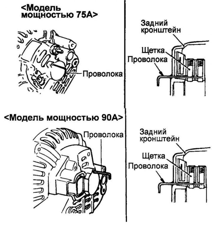
Fig. 7.45. Fixing the raised brushes
before installing the rotor into the rear bracket, insert a thin wire into the small hole in the bracket to secure the raised brushes (Fig. 7.45). Remove the wire after installing the rotor.
Installation
Place the generator in place and insert the pivot bolt (do not tighten the pivot bolt nut).
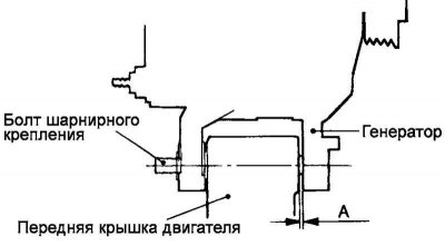
Fig. 7.46. Generator installation
Push the alternator forward and determine how many spacers (each 0.198 mm thick) need to be inserted between the front alternator strut and the front engine cover (gap "A" in Figure 7.46).
Select enough spacers so that they do not fall out when you try to insert them into the gap.
Fig. 7.47. Ventilation hole in the battery cover
Insert the spacers (into gap "A" in Figure 7.47), connect and tighten the pivot bolt nut to complete the installation.