
Contents: Disassembly ⇓ Checking the rotor ⇓ Stator check ⇓ Checking the positive terminal of…⇓ Checking the negative terminal of…⇓ Checking three diodes of the…⇓ Replacing brushes ⇓ Assembly ⇓ Battery description ⇓
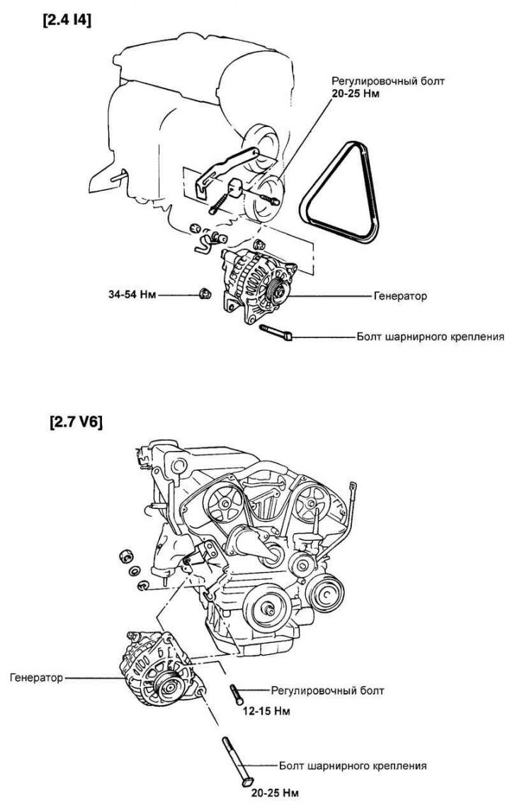
Fig. 7.24. Generator mounting
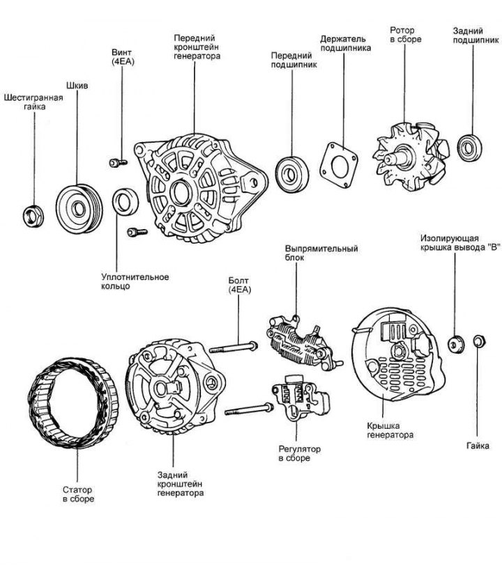
Fig. 7.25. Generator components
Disassembly
Loosen the four tie bolts.
Insert a flat-blade screwdriver between the front generator bracket and the stator and, using the screwdriver as a lever, pry (down) the front generator bracket.
Caution: Do not insert the screwdriver too deeply to avoid damaging the stator winding.
Warning! It may be difficult to remove the rear alternator bracket due to the retaining ring used to secure the rear bearing. To aid in removing the rear bracket, heat the bearing assembly with a 200 watt soldering iron.
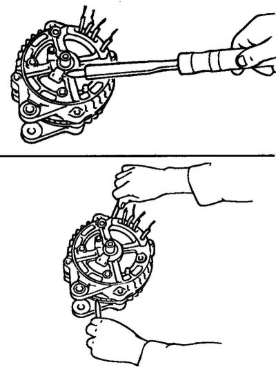
Fig. 7.26. Removing the generator bracket
Do not use a heat gun for heating, as this may damage the rectifier diodes (Fig. 7.26).
Clamp the rotor in a vice with the pulley side facing up.
Caution: Be careful not to damage the rotor with the vice jaws.
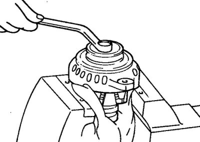
Fig. 7.27. Unscrewing the pulley mounting nut
Loosen the pulley mounting nut, remove the spring washer, then remove the pulley and spacer (Fig. 7.27).
Remove the front generator bracket and two O-rings.
Remove the rotor from the vice.
Unscrew the screws securing the brush holder and rectifier unit. Then unscrew the nut of the generator terminal "B".
Remove the stator assembly from the rear bracket
Remove the dust ring from the brush holder.
Before removing the stator, unsolder the three stator winding wires from the main diodes of the rectifier unit.
Attention! When soldering/unsoldering contacts, be careful that the heat from the soldering iron has as little effect on the diodes as possible. Perform these operations as quickly as possible.
Be careful not to apply excessive force to the diode contacts.
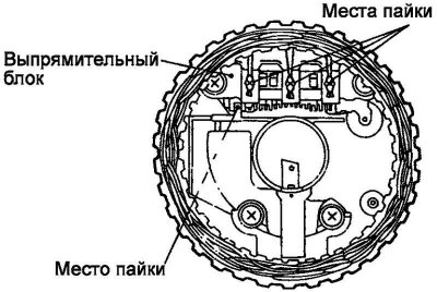
Fig. 7.28. Contact soldering locations
Before disconnecting the rectifier block from the brush holder, unsolder the two contacts soldered to the rectifier block (Fig. 7.28).
Checking the rotor
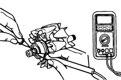
Fig. 7.29. Checking for a closed circuit between the slip rings
Check for a break in the rotor winding. Check for a closed circuit between the contact rings (Fig. 7.29). If the resistance is too low (approaching 0), this means there is a short circuit. In the event of a break in the rotor winding circuit or a short circuit, replace the rotor assembly.
Resistance: approximately 3.1 ohms.
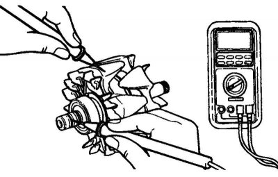
Fig. 7.30. Checking for a short circuit of the rotor winding to ground
Check for short circuit of rotor winding to ground. Check for closed circuit between slip ring and core. If there is a closed circuit (short circuit to ground), replace rotor assembly (Fig. 7.30).
Stator check
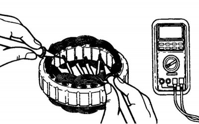
Fig. 7.31. Checking for a closed circuit between the stator winding terminals
Check for a break in the stator winding. Check for a closed circuit between the stator winding terminals. If the winding circuit is open (resistance tends to infinity), replace the stator assembly (Fig. 7.31).
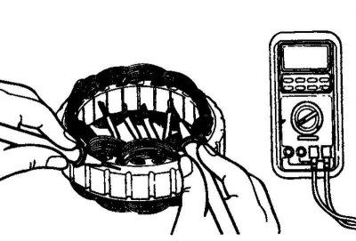
Fig. 7.32. Checking for a short circuit of the stator winding to ground
Check for short circuit of the stator winding to ground (there is no closed circuit between the stator winding and the core). If the circuit is closed (resistance tends to zero), replace the stator assembly (Fig. 7.32).
Checking the positive terminal of the rectifier block
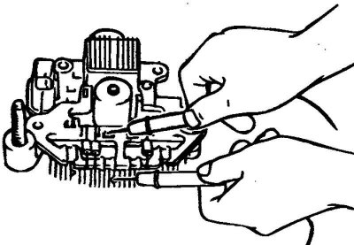
Fig. 7.33. Checking the positive terminal of the rectifier unit
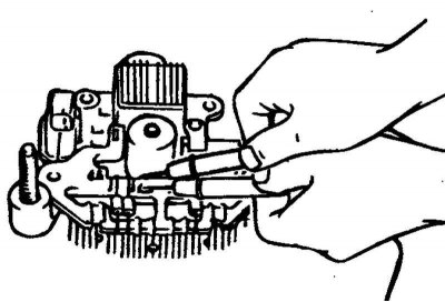
Fig. 7.34. Checking the negative terminal of the rectifier unit
Using an ohmmeter, check that the circuit between the terminal of the "positive" diodes of the rectifier unit and the terminal of the stator winding is closed (the resistance is low). Change the polarity of the ohmmeter probes and measure the resistance (if the resistance is low, i.e. the circuit is closed in both directions, then the diode is broken) (Fig. 7.34).
Replace the rectifier unit assembly.
Checking the negative terminal of the rectifier unit
Using an ohmmeter, check that the circuit between the terminal of the "negative" diodes of the rectifier unit and the terminal of the stator winding is closed (the resistance is low). Change the polarity of the ohmmeter probes and measure the resistance (if the resistance is low, i.e. the circuit is closed in both directions, then the diode is broken) (Fig. 7.34).
Replace the rectifier unit assembly.
Checking three diodes of the rectifier block
Test the three diodes by connecting an ohmmeter to both terminals of each diode. For each diode, the circuit should be complete in only one direction.
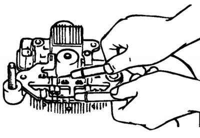
Fig. 7.35. Checking three diodes of the rectifier block
If there is no closed circuit in both directions (or if there is a closed circuit in both directions), the diode is faulty and the rectifier unit (together with the cooling radiator) must be replaced (Fig. 7.35).
Replacing brushes
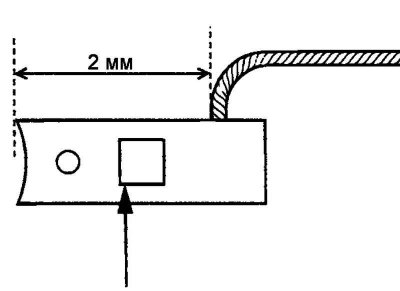
Fig. 7.36. Boundary line
Replace the brushes if the brush wear reaches the limit line. Limit line: 2 mm (Fig. 7.36).
Unsolder the brush wire and remove the generator brush with the spring.
Solder the brush wire to the brush holder.
Assembly
Assembly is carried out in the reverse order of disassembly. Please note the following:
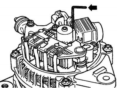
Fig. 7.37. Fixing the brushes
Before installing the rotor into the rear bracket, insert a thin wire into the small hole in the rear bracket to secure the raised brushes. The wire should be removed after installing the rotor (Fig. 7.37).
Battery description
A maintenance-free battery, as the name suggests, does not require maintenance and does not have vent plugs on the battery cells.
There is no need to add water to the electrolyte of a maintenance-free battery.
The battery is completely sealed except for a small ventilation hole in the cover.