
Contents: Adjusting the axial clearance of the…⇓ Checking the pull-in winding of the…⇓ Checking the holding winding of the…⇓ Checking the return of the traction…⇓ Idle test ⇓ Testing the power transistor ⇓ Checking the brush holder ⇓ Checking the overrunning clutch ⇓ Front and rear bracket bushings ⇓ Installing the stop and retaining…⇓ Cleaning starter parts ⇓ Checking the brush ⇓ Removal the stop ring and retaining…⇓
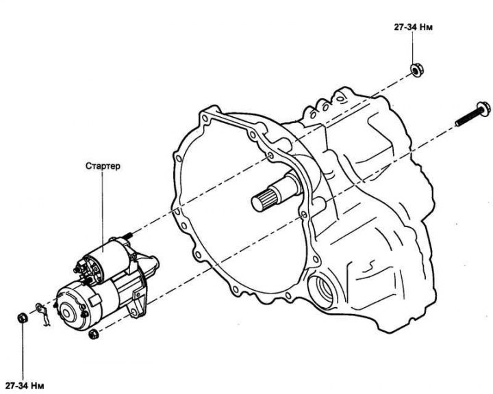
Fig. 7.53. Starter mounting
Adjusting the axial clearance of the drive gear
Disconnect the stator winding wire from the "M" terminal of the traction relay.
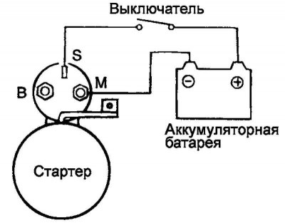
Fig. 7.54. Scheme of adjustment of axial clearance of the drive gear
Connect the wires from the 12 V terminals of the battery (via the switch) to the terminals "S" (+) and "M" (–) of the traction relay (Fig. 7.54).
Set the switch to the "On" position, which will cause the starter pinion to move forward as far as it will go.
Attention! This check must be carried out quickly, no more than 10 seconds, to prevent burnout of the starter winding.
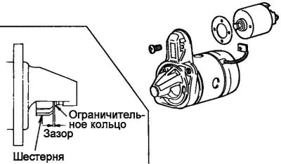
Fig. 7.55. Checking the axial clearance of the drive gear
Using a feeler gauge, measure the axial clearance between the pinion gear and the limiting ring. If the axial clearance is not within the nominal range, adjust it by installing or removing adjusting shims between the traction relay and the front starter bracket (Fig. 7.55).
Nominal clearance: 0.5–2.0 mm.
Fig. 7.56. Installation of traction relay
If the axial clearance is not within the norm, adjust it by installing or removing adjusting shims between the traction relay and the front starter bracket (Fig. 7.56).
Checking the pull-in winding of the traction relay
Disconnect the stator winding wire from the "M" terminal of the traction relay.
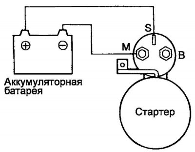
Fig. 7.57. Scheme for testing the pull-in winding of the traction relay
Connect the wires from the 12 V terminals of the battery to the "S" (+) and "M" (–) terminals of the traction relay (Fig. 7.57).
Attention! This check must be carried out quickly, no more than 10 seconds, to prevent burnout of the starter winding.
If the pinion gear extends, the pull-in winding of the traction relay is in good condition. If the pinion gear does not extend, replace the traction relay.
Checking the holding winding of the traction relay
Disconnect the stator winding wire from the "M" terminal of the traction relay.
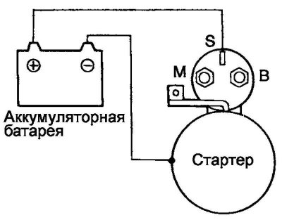
Fig. 7.58. Test diagram of the holding winding of the traction relay
Connect the wires from the 12 V terminals of the battery to the "S" (+) terminal and the starter housing (Fig. 7.58).
Attention! This check must be carried out quickly, no more than 10 seconds, to prevent burnout of the starter winding.
If the drive pinion, manually pulled out to the stop, remains in the extended position, then the holding winding is in good order. If the pinion retracts, then there is a break in the holding winding. In this case, replace the traction relay.
Checking the return of the traction relay anchor
Disconnect the stator winding wire from the "M" terminal of the traction relay.
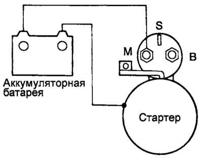
Fig. 7.59. Traction relay anchor return test diagram
Connect the wires from the 12 V terminals of the battery to the "M" terminal and the starter housing (Fig. 7.59).
Attention! This check must be carried out quickly, no more than 10 seconds, to prevent burnout of the starter winding.
Pull the pinion out by hand and release it. If the pinion immediately returns to its original position, the traction relay is OK. If not, replace the traction relay.
Idle test
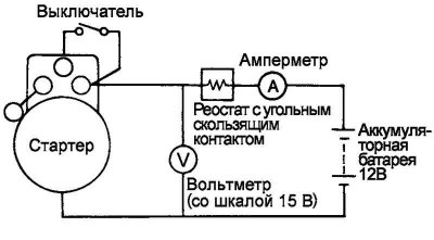
Fig. 7.60. Assembly diagram of an unloaded circuit for testing the starter in idle mode
Assemble the unloaded test circuit as shown in Figure 7.60.
Using a rheostat, adjust the battery voltage so that the voltmeter shows 11.5 V. Make sure that the maximum current consumption corresponds to the nominal value, and that the starter armature rotates freely, without jerking or jamming.
Rated current: 60A or less.
Testing the power transistor
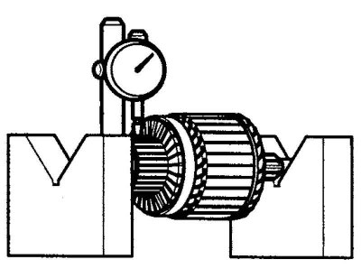
Fig. 7.61. Measuring the runout of a power transistor
Place the starter anchor in the measuring prisms. Measure the runout of the power transistor (Fig. 7.61).
Starter armature beating.
Nominal value: 0.05 mm.
Limit value: 0.1 mm.
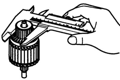
Fig. 7.62. Measuring the outer diameter of a power transistor
Measure the outside diameter (Fig. 7.62).
Power transistor diameter:
- Nominal value: 29.4 mm.
- Limit value: 28.4 mm.
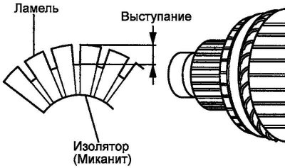
Fig. 7.63. Measuring the depth of the undercut between the lamellas of a power transistor
Measure the depth of the undercut between the lamellas of the power transistor (Fig. 7.63).
Undercut depth:
- Nominal value: 0.5 mm.
- Limit value: 0.2 mm.
Checking the brush holder
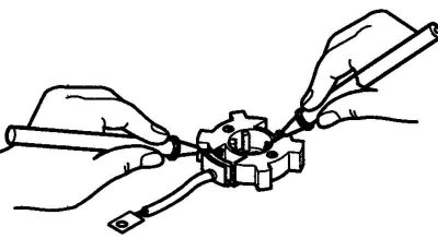
Fig. 7.64. Checking the brush holder
Check that there is no closed circuit between the plate (plus) of the brush holder and the brush holder (Fig. 7.64).
If the circuit is shorted, replace the brush holder assembly.
Checking the overrunning clutch
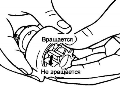
Fig. 7.65. Checking the driving gear of the overrunning clutch
Rotate the drive gear while holding the overrunning clutch housing. The gear should rotate smoothly, without jamming in one direction, and should not rotate in the opposite direction (Fig. 7.65).
Check the condition of the starter gear teeth. If the teeth are worn or chipped, replace the overrunning clutch assembly. Check the condition of the flywheel ring gear (or automatic transmission drive plate).
Front and rear bracket bushings
Assess the condition of the bushings. If there is wear or scoring, replace the corresponding bracket assembly.
Installing the stop and retaining rings
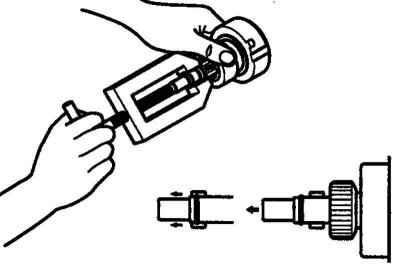
Fig. 7.66. Installing the limiting ring
First install the limiting ring, then the retaining ring on the front end of the starter armature shaft. Slide the limiting ring onto the retaining ring until it stops (Fig. 7.66).
Cleaning starter parts
Do not wash the starter anchor and stator with solvent: this may damage the insulation of the winding wires. Clean only with a dry cloth.
Do not wash the overrunning clutch by immersing it in solvent: the clutch contains grease for the entire service life and the solvent can wash out the grease.
Clean the overrunning clutch with a brush soaked in solvent, immediately remove excess solvent.
Checking the brush
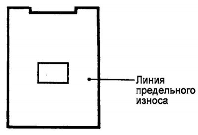
Fig. 7.67. Wear limit line
Brushes that are worn to the wear limit line or are oily should be replaced (Fig. 7.67).
Remove the worn brush, being careful not to break the brush wire.
Sand the end of the brush wire to ensure a secure soldering.
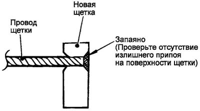
Fig. 7.68. Checking the solder of the brush wire end
Solder the end of the brush wire (Fig. 7.68).
Install the brush in place, make sure the brush is fixed with the spring
Removal the stop ring and retaining ring
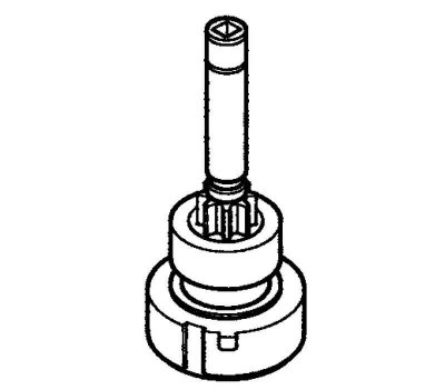
Fig. 7.69. Overrunning clutch
To remove the overrunning clutch from the starter armature shaft, it is necessary to knock the limiting ring off the retaining ring (Fig. 7.69).
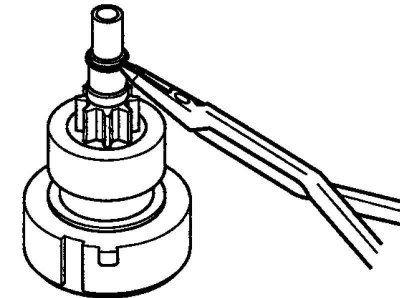
Fig. 7.70. Removing the restrictor ring
After removing the retaining ring, the stop ring can be removed from the starter armature shaft (Fig. 7.70).