
Verification procedure
1. Turn the ignition key to the "ON" position.
2. Make sure that the battery discharge indicator lamp lights up with the ignition on and the engine not running.
3. Disconnect the excitation winding resistor connector.
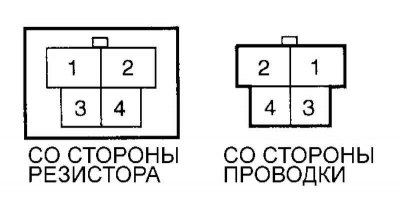
Fig. 7.9. Power supply circuit test connector pins
Connect the ohmmeter probes to terminals 1 and 3 (on the resistor side). Connect the (+) ohmmeter lead to terminal 3 and the (–) ohmmeter lead to terminal 1 (Fig. 7.9).
Warning! If the ohmmeter probes are connected incorrectly, the measurement result will be incorrect. Make sure that the instrument probes are connected correctly and securely.
Analysis of results
If the circuit is closed when the conditions of points 2 and 3 are met, then the circuit is in good condition.
If the circuit is open when the conditions of points 2 and 3 are met, then the circuit is faulty, but the battery is normal.
If the circuit is open only when the conditions in point 2 are met, then the low battery indicator lamp circuit must be checked and repaired.
If the circuit is open only when the conditions in point 3 are met, check and, if necessary, replace the excitation winding resistor.
Note: If the circuit is open only when one of the conditions (2 or 3) is met, the system will still be operational. However, the faulty circuit should be repaired to make the charging system work more reliably.
The original article is posted on the portal: www.HyundaiBook.ru