
Contents: Checking for a short circuit of the…⇓ Checking for short circuit in the…⇓ Checking for breaks in the armature…⇓ Checking for breaks in the stator…⇓ Checking for a short circuit of the…⇓ Checking the brush ⇓ Checking the brush holder ⇓ Checking the overrunning clutch ⇓ Replacing brushes ⇓ Replacing the rear bracket bushing ⇓ Assembly ⇓ Checking the starter relay ⇓ Checking the Clutch Pedal Switch…⇓
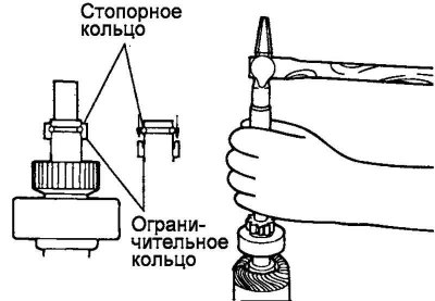
Fig. 7.62. Removing the retaining and limiting rings
To remove the overrunning clutch from the starter armature shaft, it is necessary to remove the retaining and limiting rings (Fig. 7.62).
Pull (down toward the pinion gear) the stop ring off the retaining ring. The stop ring can then be removed from the starter armature shaft.
Checking for a short circuit of the armature winding to ground
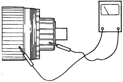
Fig. 7.63. Checking the resistance between each commutator lamella and the armature core
Using an ohmmeter, check for a closed circuit (resistance) between each commutator plate and the armature core (Fig. 7.63).
If the circuit is closed (resistance tends to zero), replace the starter armature assembly.
Checking for short circuit in the armature winding
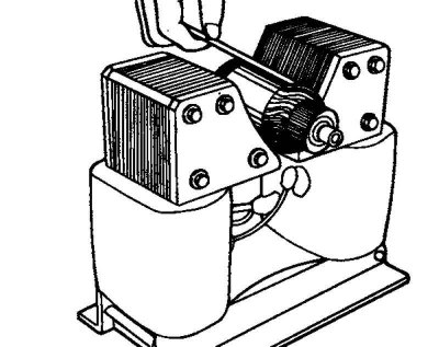
Fig. 7.64. Checking for short circuit in the armature winding
Install the armature in a growler (a device for checking the winding of the starter and generator). If there are signs of a short circuit, replace the armature. If the thin steel plate located near the armature housing vibrates when the starter armature rotates, then the armature winding is short-circuited (Fig. 7.64).
Checking for breaks in the armature winding
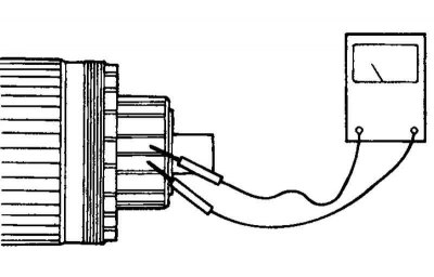
Fig. 7.65. Checking for breakage in the armature winding
Using an ohmmeter, check for a closed circuit (resistance) between the collector lamellas (Fig. 7.65).
If the circuit is open, then there is a break in the armature winding.
Checking for breaks in the stator winding

Fig. 7.66. Checking for breaks in the stator winding
Using an ohmmeter, check for a closed circuit between the brush terminals (Fig. 7.66).
If the circuit is open, there is a break in the stator winding. In this case, replace the starter housing together with the stator winding.
Checking for a short circuit of the stator winding to ground
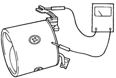
Fig. 7.67. Checking for a short circuit of the stator winding to ground
With the winding installed on the stator, check for a closed circuit between the brush terminal (stator winding) and the starter housing using an ohmmeter (Fig. 7.67).
If the circuit is shorted, replace the starter housing assembly with the stator winding.
Checking the brush
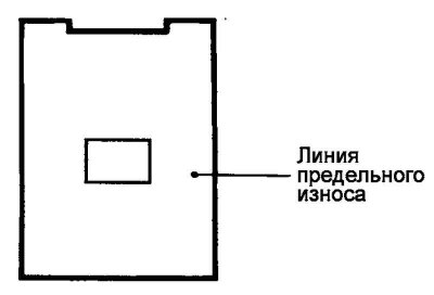
Fig. 7.68. Line of permissible wear of brushes
Brushes worn below the maximum permissible line should be replaced (Fig. 7.68).
Checking the brush holder
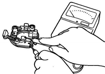
Fig. 7.69. Checking for a closed circuit between the plate (plus) of the brush holder and the brush holder
Check that there is no closed circuit between the plate (plus) of the brush holder and the brush holder (Fig. 7.69).
If the circuit is shorted, replace the brush holder assembly.
Checking the overrunning clutch
Check the pinion gear and flywheel ring gear (manual transmission models) or torque converter (automatic transmission models) for scoring or excessive wear.
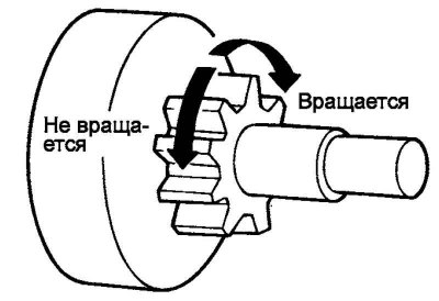
Fig. 7.70. Checking the overrunning clutch
Rotate the drive gear while holding the overrunning clutch housing. The gear should rotate smoothly, without jamming in one direction, and should not rotate in the opposite direction (Fig. 7.70).
Replacing brushes
Remove the worn brush, being careful not to damage the brush wire.
The article is borrowed from an online resource [HYUNDAIBOOK]
Sand the end of the brush wire to ensure a strong solder joint.
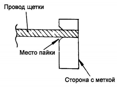
Fig. 7.71. Soldering point of the brush wire end
Solder the end of the brush wire (Fig. 7.71).
Replacing the rear bracket bushing
Before removing the bushing, measure and record the depth of the bushing in the bracket.
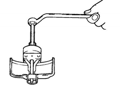
Fig. 7.72. Removing the bushing
The bushing can be removed using a puller as shown in Figure 7.72.
Press in the new bushing so that its seating depth corresponds to the value recorded earlier.
Assembly
Install the overrunning clutch onto the front end of the starter armature shaft.
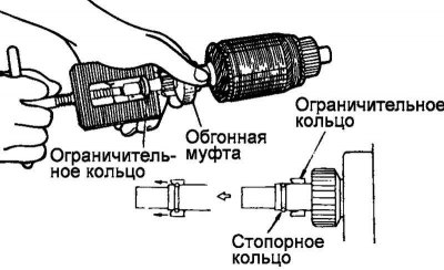
Fig. 7.73. Installing the limiting ring
First install the limiting ring, then the retaining ring on the front end of the starter armature shaft. Place the overrunning clutch limiting ring on the retaining ring until it stops (Fig. 7.73).
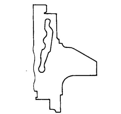
Fig. 7.74. Lever location
When installing the lever into the front starter bracket, pay attention to the position of the lever. If the lever is installed incorrectly (i.e. in the opposite direction), the pinion remains in the extended position and will not operate correctly (Fig. 7.74).
Checking the starter relay
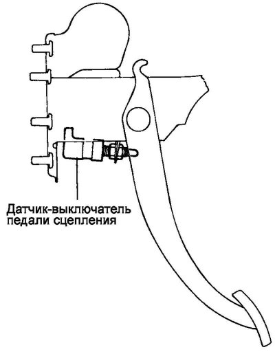
Fig. 7.75. Starter relay test diagram
Remove the starter relay and check the circuit condition between the terminals according to the table. If the circuit condition differs from the specified one, replace the relay (Fig. 7.75).
Checking the Clutch Pedal Switch Sensor
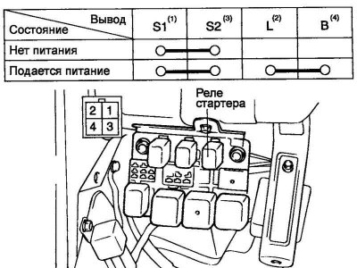
Fig. 7.76. Clutch pedal switch sensor test diagram
Check the condition of the circuit between the terminals according to the table (Fig. 7.76).