
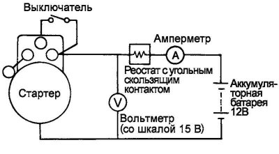
Fig. 7.61. Assembly diagram of an unloaded circuit for testing the starter in idle mode
Assemble the unloaded test circuit as shown in Figure 7.61.
Using a rheostat, adjust the battery voltage so that the voltmeter shows 11.5 V. Make sure that the maximum current consumption corresponds to the nominal value, and that the starter armature rotates freely, without jerking or jamming.
Rated current: 60A or less.