
Contents: Actions with the charging system…⇓ Charging the system with refrigerant…⇓ Charging the system with liquid…⇓ Checking the tightness of the system ⇓ Checking the cooling capacity of the…⇓
Note: Each time the system is opened, a vacuum must be created to prevent air and moisture from entering. After installing any component, the vacuum in the system must be maintained for approximately 15 minutes. Components of the system opened for repair must be under vacuum for 30 minutes.
If the engine does not run, perform the following procedures.
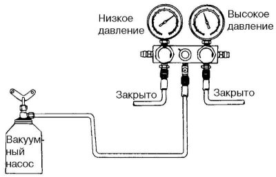
Fig. 8.60. Position "closed"
Attach a set of test pressure gauges to the compressor fittings. Close the high and low pressure line valves (Fig. 8.60).
Make sure the refrigerant has been drained from the system.
Connect the center hose of the pressure gauge kit to the inlet of the vacuum pump.
Turn on the vacuum pump and open the high and low pressure valves.
After about 10 minutes, check that the low pressure gauge shows a vacuum below 94.39 kPa (0.96 kgf/cm²). If a vacuum cannot be obtained, this indicates a leak in the system. In this case, eliminate the leak as described below.
1. Close both valves of the pressure gauge set and turn off the vacuum pump.
2. Charge the system with refrigerant from the container (approximately 0.4 kg).
3. Locate the leak using a leak detector.
4. Drain the refrigerant again and create a vacuum in the system. If no leaks are found, continue creating a vacuum in the system.
Turn on the vacuum pump.
Open both valves of the pressure gauge set until a vacuum of 94.39 kPa (0.96 kgf/cm²) is created (Fig. 8.61).
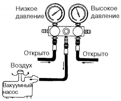
Fig. 8.61. Position "open"
After the low pressure gauge shows a vacuum of about 94.39 kPa (0.96 kgf/cm²), continue to create a vacuum for 15 minutes.
After the system has been under vacuum for 15 minutes, close both valves of the pressure gauge set and turn off the vacuum pump. Disconnect the hose from the vacuum pump. The system is ready for charging with refrigerant.
Actions with the charging system valve
Fig. 8.62. Installation diagram when operating with the system charging valve
Before connecting the valve to the refrigerant container, turn its handle counterclockwise until it stops.
Set the disc to its highest position by turning it counterclockwise.
Connect the central hose to the valve nipple.
Turn the valve handle clockwise to create a hole in the sealed top.
Loosen the nut securing the central hose to the central fitting of the control pressure gauges.
Release the air for a few seconds, then tighten the nut.
Charging the system with refrigerant vapor
Set the refrigerant container valve to the position specified above in the section "Operations with the system charging valve".
Note: This operation is performed to charge the system with refrigerant in a vapor state through the low-pressure circuit. When the container with refrigerant is in a vertical position, the latter is supplied to the system in the form of vapor.
Open the low pressure circuit valve and adjust its position so that the pressure on the low pressure gauge does not exceed 412 kPa (4.2 kgf/cm²).
To make the vapor pressure in the refrigerant container slightly higher than the system pressure, place the container in a vessel with warm water (at a temperature of about 40°C).
Run the engine at fast idle and turn on the air conditioner.
Note: Keep the refrigerant container in an upright position to prevent liquefied refrigerant from entering the system through the suction line, which may cause damage to the compressor.
Fig. 8.63. Low pressure circuit "closed" position
Fill the system with the required amount of refrigerant, then close the low pressure circuit valve (Fig. 8.63).
Amount of refrigerant charged: 500±25g.
When charging the refrigerant at a reduced rate, immerse the refrigerant container in warm water (at a temperature of about 40°C).
Caution! Never immerse the container with refrigerant in water heated to a temperature above 52°C.
Attention! It is prohibited to heat the container with a blowtorch or in a drying chamber.
Charging the system with liquid refrigerant
After purging the system with vacuum, close the high and low pressure valves completely.
Note: This operation is performed to charge the discharged system with refrigerant in liquid form through the high-pressure circuit. With the container upside down, the refrigerant is supplied to the system in liquid form.
Warning! It is prohibited to charge the system through the high-pressure circuit when the engine is running. When charging with liquid refrigerant, do not open the low-pressure valve.
Set the refrigerant container valve to the position specified above in the section "Operations with the system charging valve".
Open the high pressure valve fully by placing the refrigerant container upside down.
Charge the system with the required amount of refrigerant, determining its mass using a scale. Overcharging will result in excess discharge pressure (in the high-pressure circuit). When charging is complete, close the high-pressure valve.
Amount of refrigerant charged: 500±25g.
After charging the system with the required amount of refrigerant, close the control pressure gauge valve.
Use a leak detector to check for leaks in the system.
Note: It is recommended to check the operation of the system before removing the test gauges.
Checking the tightness of the system
In all cases where a refrigerant leak is suspected or work is performed involving disconnecting components or loosening connections, perform a system leak test using an electronic leak detector.
Check the tightening torque of the pipe connections. If the tightening is loose, tighten the connections to the specified torque. Use a leak detector to make sure there are no gas leaks.
The material is reprinted from another resource: HyundaiBook.ru
If the leak is not eliminated after tightening the connection, discharge the system, disconnect the connection and check the sealing surfaces for damage. Even slightly damaged connection parts must be replaced.
Check the amount of compressor oil and restore it to normal if necessary.
Charge the system and check for leaks. If no leaks are found, vacuum purge and charge the system.
Checking the cooling capacity of the system
Install control pressure gauges.
Start the engine and let it run at 2000 rpm, set the temperature switch to the position corresponding to the supply of the coolest air into the passenger compartment, and the fan switch to the position corresponding to the maximum rotation speed.
Open all windows and doors.
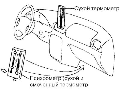
Fig. 8.64. Installing a dry thermometer in the nozzle supplying cooled air to the cabin
Place a dry thermometer in the nozzle supplying cooled air to the passenger compartment (Fig. 8.64).
Place the psychrometer at the air intake point of the air conditioner refrigeration circuit.
Check the high pressure gauge readings, which should be between 1.373–1.575 kPa (14–16 kgf/cm²). If the readings exceed the upper limit, pour water on the condenser. If the readings are below the lower limit, cover the front of the condenser.
Check the dry thermometer readings, which should be within 25–35°C.
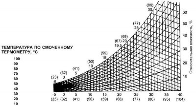
Fig. 8.65. Psychrometric graph
Determine the relative humidity of the air using a psychrometric chart by comparing the temperatures of the wet and dry thermometers of a psychrometer placed at the air intake point of the air conditioner (Fig. 8.65).
Note: By determining the wet and dry bulb temperatures at the evaporator inlet, the relative humidity can be determined. Example: the dry and wet bulb temperatures at the evaporator inlet are 25°C and 19.5°C, respectively. The intersection point of the corresponding dotted lines on the graph gives the relative humidity value (60%).
Determine the temperature using a dry thermometer placed in the nozzle supplying cooled air to the passenger compartment and calculate the difference between the temperature values using the dry thermometer at the air intake and the dry thermometer at the air outlet to the passenger compartment.
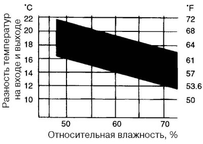
Fig. 8.66. Relative humidity calculation graph
Make sure that the intersection point of the relative humidity and temperature difference lines is within the black shaded area, which indicates that the cooling capacity characteristics are within the standard (Fig. 8.66).