
Contents: Removal ⇓ Installation ⇓
Removal
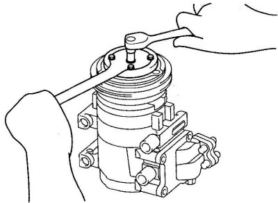
Fig. 8.67. Unscrewing the hub mounting bolt
Use a wrench to loosen the hub mounting bolt (Fig. 8.67).
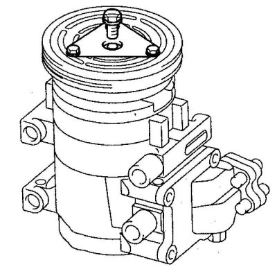
Fig. 8.68. Removing the hub and adjusting shim from the compressor shaft
Remove the hub and adjusting shim from the compressor shaft. If removal is difficult, screw an 8 mm bolt into the hole in the end of the shaft and remove the hub from the shaft (Fig. 8.68).
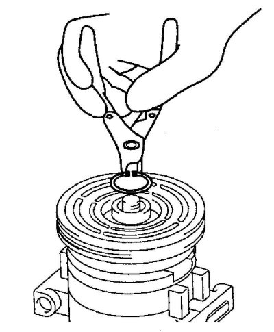
Fig. 8.69. Removing the pulley retaining ring
Remove the pulley retaining ring (Fig. 8.69).
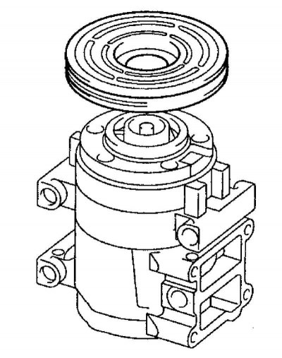
Fig. 8.70. Removing the pulley from the compressor
Remove the pulley assembly with the bearing from the compressor (Fig. 8.70).
Installation
Clean the pulley and bearing mounting surfaces in the compressor head to remove any dirt or rust.
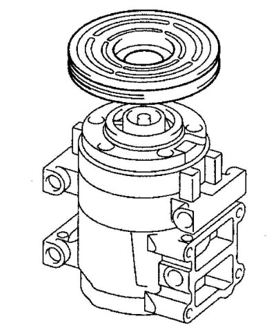
Fig. 8.71. Installing the pulley and bearing on the compressor
Install the pulley and bearing on the compressor (Fig. 8.71).
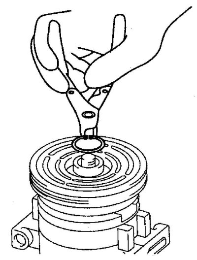
Fig. 8.72. Installing the retaining ring
Install the retaining ring with the chamfer facing outward (Fig. 8.72).
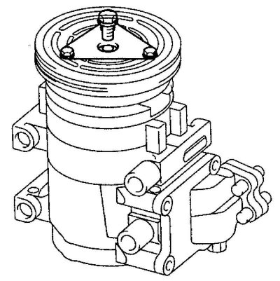
Fig. 8.73. Installing the adjusting shim
Install the adjusting lining of the required thickness with the splined grooves facing inward, install the hub on the end of the compressor shaft (Fig. 8.73).
Screw the new hub mounting bolt into the end of the compressor shaft and tighten it to the specified torque
Tightening torque: 11–14 Nm.
Warning! Do not use pneumatic tools.
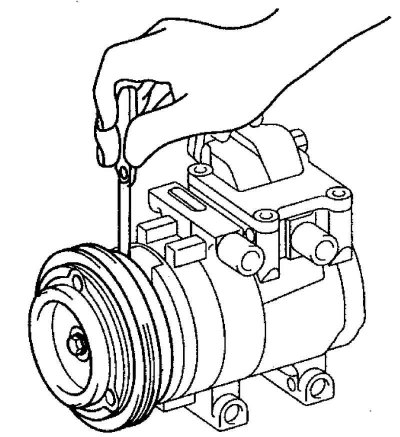
Fig. 8.74. Checking the clearance between the clutch hub and the pulley surface
Use a feeler gauge to check the gap between the clutch hub and the pulley surface (Fig. 8.74).
Coupling installation gap: 0.05–0.08 mm.
Check the clearance at 3 points around the pulley circumference.
If the hub installation clearance is not within the specified limits, adjust it by installing an adjusting shim of the appropriate thickness.