
Contents: Technical data ⇓ General information ⇓
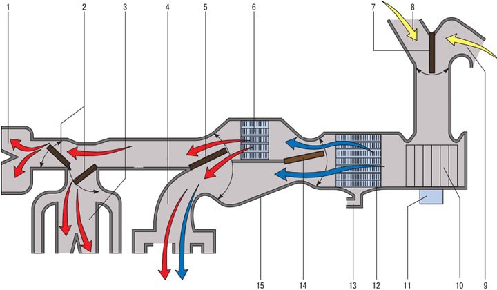
Air flow diagram in the ventilation, heating and air conditioning system: 1 - windshield blower deflectors; 2 - air flow distribution flaps to the windshield deflectors and instrument panel deflectors; 3 - instrument panel deflectors; 4 - air ducts for heating the driver's and passengers' footwells; 5 - air flow distribution flap to the instrument panel deflectors and to the heating air ducts for the driver and passenger footwells; 6 - heater radiator; 7 - recirculation system flap; 8 - air intake box; 9 - air intake in the car interior; 10 - fan impeller; 11 - Fan motor; 12 - air conditioner evaporator; 13 - drainage hole for condensate draining; 14 - temperature regulator flap; 15 - heating and air conditioning system unit housing
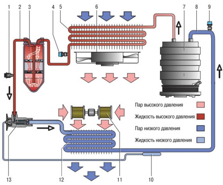
Schematic diagram of the movement of refrigerant in the air conditioning system: 1 - combined pressure sensor; 2 - section of high pressure pipeline; 3 - receiver-dryer; 4 - high pressure line service valve; 5 - condenser (air conditioning radiator); 6 - condenser and radiator fan of the cooling system; 7 - air conditioning compressor; 8 - low pressure pipeline section; 9 - Low pressure line service valve; 10 - thermobulb; 11 - heater fan; 12 - evaporator; 13 - thermostatic valve
Technical data
| Heater | Maximum heating power, kcal/h | 4 500 ±10% |
| Cooling | Maximum cooling capacity, kcal/h | 4100±410 |
| Compressor | Type | 10RA15S |
| Performance, cm³ | 155,3 | |
| Condenser | Cooling capacity, kcal/h | 11000 |
| Electromagnetic clutch | Static friction, N·m | 5,4 |
| Triple pressure sensor | High pressure, kg/cm² | OFF:32 |
| Average pressure, kg/cm² | OFF:14 | |
| Low pressure, kg/cm² | OFF:2 | |
| Evaporator | Turning the air conditioner on/off | OFF:1,5±0,6°C |
| Coolant | Type | R134a |
| Quantity, g | 500±25 |
General information
The compressor, driven by the car's engine, compresses the gaseous refrigerant to high pressure, significantly increasing the temperature of the refrigerant. The compressed and heated refrigerant is then fed to the condenser, which is mounted on the radiator of the cooling system. The condenser cools the gaseous refrigerant, which turns into a liquid. The liquid refrigerant enters the receiver/dryer, where water is separated from it, then feeds the liquid to the evaporator, located in the heater unit in the car's interior. In the evaporator, the liquid refrigerant evaporates, turning into a gaseous state, and reduces the temperature of the air entering the interior. The gaseous refrigerant then enters the compressor and the cycle repeats again.
[This publication is based on information from the portal HYUNDAIBOOK]
The air conditioner relay controls the electrical circuits of the condenser fan and the air conditioner compressor. The relay is controlled by the engine control unit. If the coolant exceeds a certain temperature, the engine control unit turns off the relay, which turns off the air conditioning system. When the engine is started or the vehicle accelerates, the engine control unit turns off the relay, which turns off the air conditioning system for 5 seconds.
The fan blows air through the evaporator core, increasing the flow of cooled air into the vehicle. The fan speed is determined by the position of the fan switch and the resistor pack.
The air conditioning compressor is the primary element of the air conditioning system. If the air conditioning compressor fails, there is no compression and movement of the refrigerant through the air conditioning system circuit. The air conditioning compressor is driven by a belt from the crankshaft pulley.
The air conditioning compressor clutch engages the compressor. The clutch is electromagnetically controlled.
The condenser is mounted in front of the radiator. The condenser fan increases the air flow through the condenser.
The fan/evaporator assembly contains the fan motor, air conditioner relay, evaporator core and expansion valve.
The evaporator core performs the functions of cooling and drying the air. When the air is cooled, moisture from the air is deposited on the evaporator and cooled dry air enters the car interior.
The expansion valve allows the high-pressure liquid refrigerant to expand as it enters the evaporator. The valve allows a certain amount of liquid refrigerant to pass through to prevent flooding of the evaporator.
The dried air can be reheated by passing through the heater core. The heater core is heated by the hot coolant passing through it.
The receiver/dryer receives liquid refrigerant from the condenser, where water is removed from it and then the refrigerant flows to the evaporator.
The air conditioning system is filled with R-134a refrigerant.