

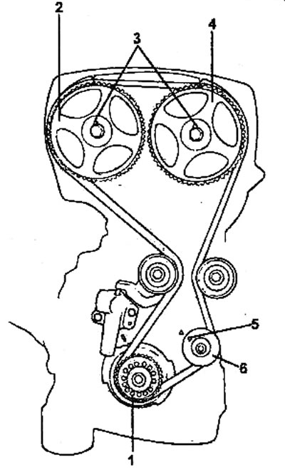
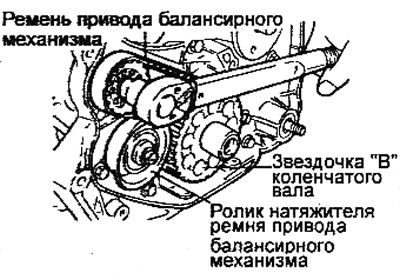
Timing belt.
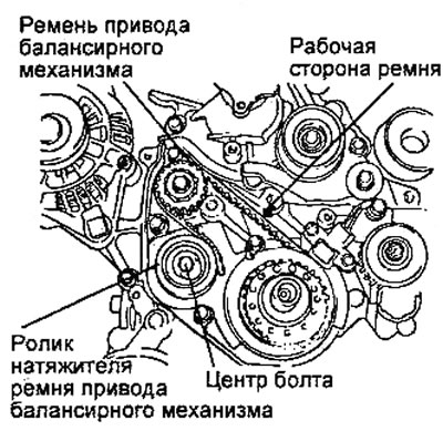
1 - accessory drive belts, 2 - coolant pump pulley, 3 - alternator adjusting bar, 4 • upper timing belt cover, 5 - TRM drive belt, 6 - coolant pump, 7 - crankshaft pulley, 8 - rear left timing belt cover (upper), 9 - rear left timing belt cover (lower), 10 - right balance shaft sprocket, 11 - camshaft sprocket, 12 - automatic tensioner lever, 13 - timing belt tensioner roller, 14 - automatic tensioner, 15 - special washer, 16 - crankshaft sprocket, 17 - oil pump sprocket, 18 - guide roller, 19 - guide plate, 20 - balance beam drive belt tensioner roller, 21 - balance beam drive belt mechanism, 22 - crankshaft sprocket "B", 23 - plug.
Removal
Caution: Turn the crankshaft clockwise until the timing marks on the crankshaft sprocket and cylinder block are aligned to set the piston of cylinder No.1 to TDC of the compression stroke. In this case, the marks on the camshaft sprockets must be aligned with the corresponding timing marks on the cylinder head cover, and the camshaft sprocket alignment pins must be facing upward.
1. Remove the accessory drive belts. Remove the crankshaft pulley and coolant pump pulley.
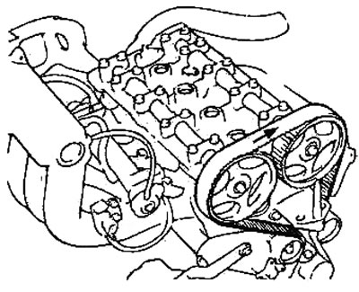
Timing belt - general view.
1 - crankshaft sprocket, 2 - exhaust camshaft sprocket, 3 - alignment pin, 4 - intake camshaft sprocket, 5 - alignment marks, 6 - oil pump sprocket.
2. Remove the front timing belt covers.
3. Align the camshaft and crankshaft sprocket marks with the timing marks.
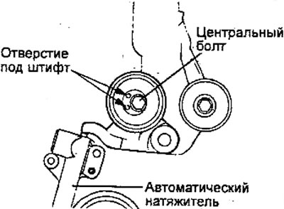
4. Remove the automatic timing belt tensioner and move the tensioner roller away from the timing belt.
5. Remove the timing belt.
Note: If the timing belt is reused, it is necessary to mark with chalk on the reverse (non-working) surface of the belt an arrow indicating the direction of rotation (or the location of the crankshaft pulley) so as not to confuse the direction of rotation when installing the belt.
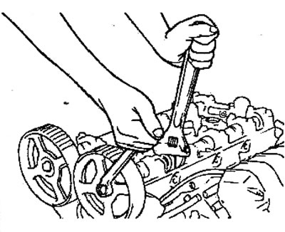
6. If necessary, remove the camshaft sprockets.
Note: Be careful not to damage the cylinder head with the wrench when removing the camshaft sprocket.
7. If necessary, remove the oil pump sprocket.
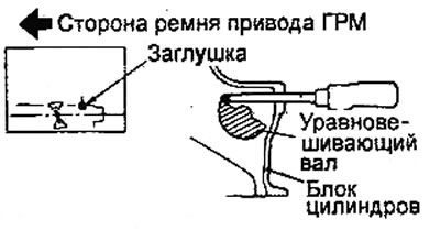
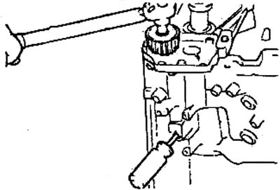
- a) Before removing the oil pump sprocket nut, unscrew the plug on the left side of the cylinder block and insert an 8 mm screwdriver into the plug hole to fix the balance shaft in the appropriate position. The screwdriver should go in to a depth of more than 60 mm.
- b) Unscrew the oil pump sprocket mounting nut and remove the sprocket.
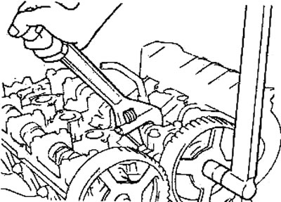
8. Loosen the right balance shaft sprocket mounting bolt so that it can be further unscrewed by hand.
9. Remove the tensioner roller and the balance mechanism drive belt.
Caution: After removing the balancer drive belt, do not attempt to loosen the balance shaft sprocket bolt by holding the balance shaft sprocket with pliers or the like.
Note: If the balancer drive belt is reused, it is necessary to mark with chalk on the reverse (non-working) surface of the belt an arrow indicating the direction of rotation (or the location of the crankshaft pulley), so as not to confuse the direction of its rotation when installing the belt.
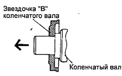
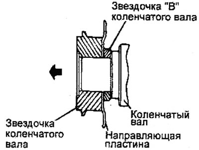
10. Remove the crankshaft sprocket "B" (balance shaft drive sprocket).
Examination
Sprockets, timing belt tensioner roller and guide roller
1. Check the camshaft sprocket, crankshaft sprocket, timing belt tensioner pulley and idler pulley for excessive wear, cracks or damage. Replace if necessary.
2. Check the ease and smoothness of rotation of the timing belt tensioner roller and guide roller, and make sure there is no excessive play or extraneous noise when rotating. Replace if necessary.
3. Replace the roller if traces of grease leaking from its bearing are detected.
Automatic tensioner
1. Check for fluid leaks from the tensioner. Replace the tensioner if necessary.
2. Check the tensioner rod for wear or damage. Replace the tensioner if necessary.
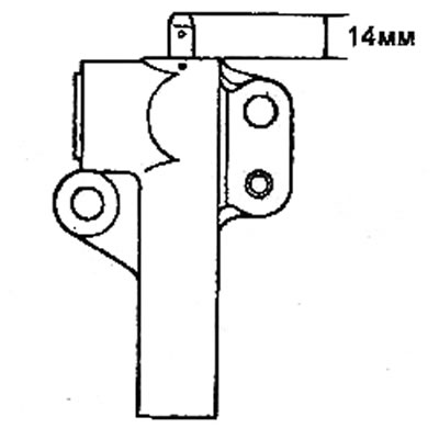
3. Measure the rod protrusion from the tensioner body. If the protrusion does not correspond to the nominal value, replace the tensioner.
- Nominal value: 14.0 mm
4. Place the tensioner in a vice with soft metal jaw pads. Slowly insert the tensioner rod into the tensioner housing. If the rod movement force is low, replace the automatic tensioner. There should be significant resistance to rod movement. Perform the check in several stages.
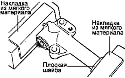
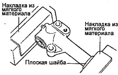
Note: The automatic tensioner must be installed at a right angle to the surface of the vice jaws. To prevent damage to the tensioner, use vice jaw pads made of soft material.
5. Preparing the tensioner for installation if the tensioner rod is in the fully extended position.
- a) Install the automatic tensioner in a vice at a right angle to the surface of the vice jaws (without distortions). Place a flat washer under the tensioner body.
- b) Gradually tightening the vice, slowly push the rod into the tensioner body until the holes in the body and the rod are aligned.
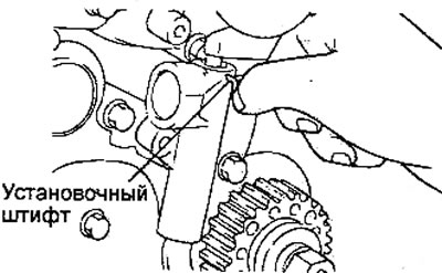
- c) Insert the dowel pin into the holes in the body and stem to secure the stem.
Caution: Do not remove the locating pin from the hole in the automatic tensioner housing.
Installation
Attention:
- Since water or oil can seriously reduce the life of the timing belt, when removing parts, ensure that the timing belt, sprockets and rollers are clean and dry, never wash them. Contaminated parts must be replaced.
- If any of the parts are oily, check for oil leaks through the seals (including the front camshaft seal).
- Check the condition and smooth rotation of the tensioner roller.
- If a previously used timing belt is being installed, check its condition (see the relevant section in the chapter "Maintenance and general check and adjustment procedures").
1. Install the crankshaft sprocket "B" (balance shaft drive sprocket) onto the crankshaft.
Caution: Pay attention to the installation direction of the sprocket flange. If the sprocket or flange is not installed correctly, the balancer drive belt may be damaged.
2. Installing the right balance shaft sprocket.
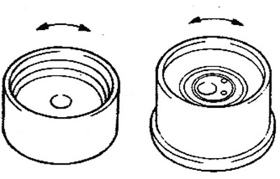
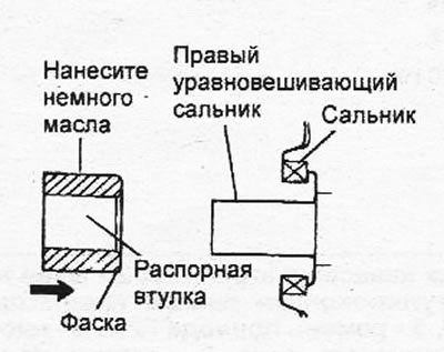
- a) Apply engine oil to the outer surface of the spacer sleeve and install it onto the right balance shaft. Make sure that the installation direction of the spacer sleeve is as shown in the figure.
- b) Install the sprocket onto the right balance shaft and pre-tighten the sprocket mounting bolt by hand.
3. Installing the balance mechanism drive belt.
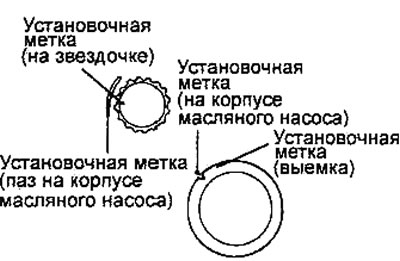
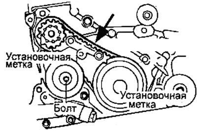
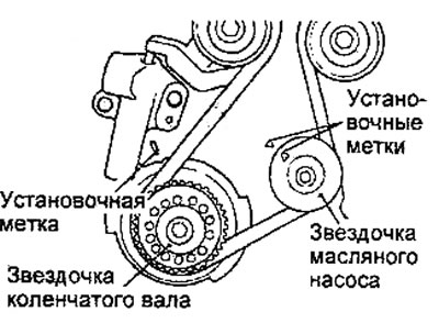
- a) Align the marks on the balance shaft sprockets with the timing marks on the oil pump housing.
- b) Install the balance mechanism drive belt without slack in the working branch.
- c) Install the balancer drive belt tensioner roller so that its center is located to the left of the mounting bolt and the roller flange is directed toward the crankshaft pulley.
- d) Align the mark on the right balance shaft sprocket with the timing mark on the oil pump housing.
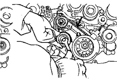
- d) Turn the tensioner upwards to tighten the balancer drive belt so that the working branch of the belt does not sag. In this position, tighten the tensioner mounting bolt. Be careful when tightening the tensioner mounting bolt, do not allow the shaft to rotate. If the shaft rotates, the belt will be over-tightened.
4. Check that the sprocket marks are aligned with the timing marks.
5. Check the tension of the balance mechanism drive belt.
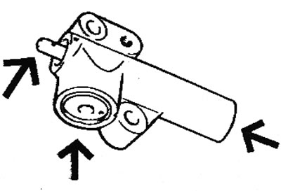
Make sure that when you press with your finger in the middle of the belt span in the direction indicated by the arrow, the belt deflection corresponds to the nominal value.
- Belt deflection: 5-7 mm
6. Installing the crankshaft sprocket (for timing drive).
- a) Install the guide plate and crankshaft sprocket. Make sure the installation direction of the parts matches the figure.
Caution: Pay attention to the installation direction of the guide plate. If the guide plate is not installed correctly, the drive belt will be torn.
- b) Install the special washer and crankshaft sprocket mounting bolt. Tighten the bolt to the specified torque.
- Tightening torque: 110-130 Nm
7. Installing the oil pump sprocket.
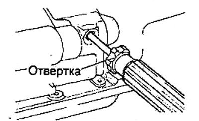
- a) Insert a screwdriver into the access hole on the left side of the cylinder block to secure the left balance shaft.
- b) Install the oil pump sprocket and tighten its mounting nut to the specified torque.
- Tightening torque 50-60 Nm
8. Install the camshaft sprocket and tighten its mounting bolt to the specified torque.
- Tightening torque: 80-100 Nm
9. Install the automatic tensioner.
Caution: Do not remove the locating pin from the hole in the automatic tensioner housing.
10. Install the roller on the tensioner arm. Tighten the mounting bolt to the specified torque.
- Tightening torque: 43-55 Nm
11. Turn the camshaft sprockets so that the sprocket alignment pins are at the top. Align the camshaft sprocket marks with the timing marks.
Note:
- If the camshaft timing marks do not align with the timing marks on the cylinder head before installing the belt, do not turn the camshaft sprocket more than 2 teeth in each direction. Turning the camshaft sprocket more than 2 teeth may cause the valves and pistons to touch.
- If it is necessary to turn the camshaft sprocket more than 2 teeth, carefully turn the crankshaft counterclockwise a certain amount before turning the camshaft sprocket. After aligning the camshaft sprocket mark, return the crankshaft to its original position (TDC).
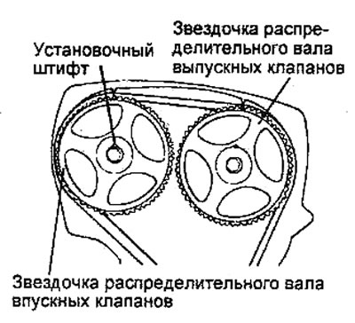
Note: If the camshaft sprockets have been replaced, check that the camshaft sprocket identification marks match the engine.
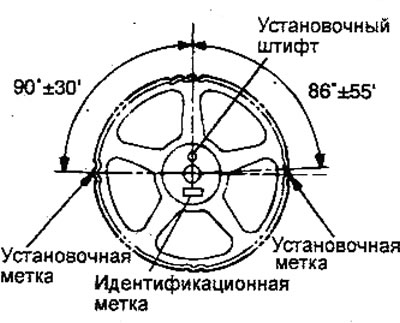
12. Align the crankshaft mark with the timing mark and align the oil pump sprocket mark with the timing mark.
13. Installing the timing belt.
- a) Install the timing belt counterclockwise onto the tensioner pulley and crankshaft sprocket. Hold the belt on the tensioner pulley with your left hand.
- b) While pulling the belt with your right hand, place it on the oil pump sprocket.
- c) Place the belt on the guide roller.
- d) Place the belt on the intake camshaft sprocket.
- d) Turn the exhaust camshaft sprocket clockwise by one tooth until the sprocket mark aligns with the timing mark.
- e) Using both hands, tighten the belt and place it on the exhaust camshaft sprocket.
14. Raise the automatic tensioner roller slightly to remove any slack in the belt, then pre-tighten the roller bolt.
15. Check that all sprocket marks are aligned with the timing marks.
16. Remove the dowel pin from the automatic tensioner housing.
17. Turn the crankshaft two revolutions clockwise and leave it stationary for approximately 15 minutes.
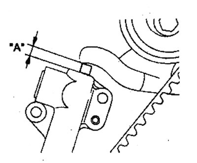
18. Measure the tensioner rod protrusion "A" (the distance between the lever and the tensioner body) and ensure that it is within the specified range.
- Nominal value: 6-8 mm
19. Tighten the tensioner roller bolt to the specified torque.
- Tightening torque: 43-55 Nm
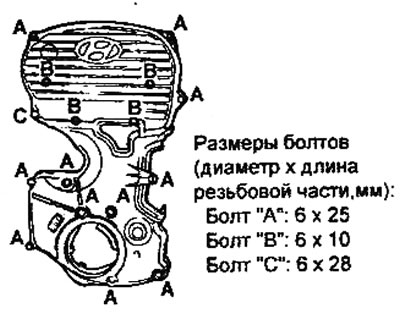
20. Install the upper and lower timing belt covers and tighten the cover mounting bolts to the specified tightening torque.
Tightening torque:
- Bolts "A" and "B": 8-10 Nm
- Bolt "C": 10-12 Nm
21. Install the crankshaft pulley, coolant pump pulley and install the accessory drive belts.
22. Adjust the tension of the drive belts of the attachments.