


Contents: Removal ⇓ Installation ⇓
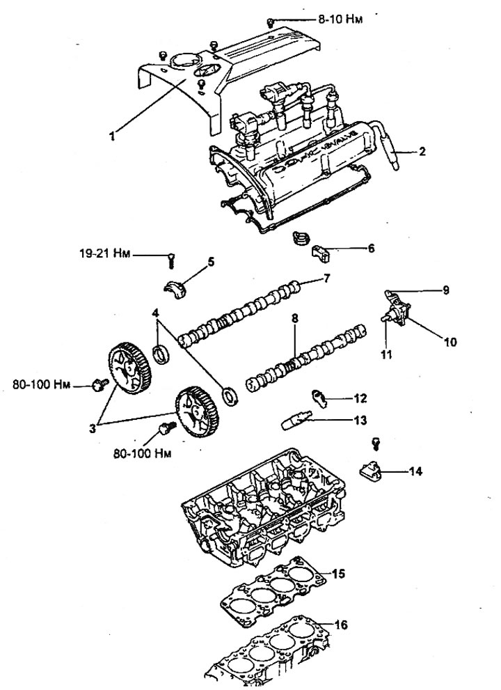
Replacing the cylinder head gasket.
1 - center cover, 2 - positive crankcase ventilation hose, 3 - camshaft sprocket, 4 - camshaft oil seal, 5 - front bearing cover, 6 - rear bearing cover, 7 - intake camshaft, 8 - exhaust camshaft, 9 - camshaft position sensor, 10 - camshaft position sensor mounting bracket, 11 - camshaft position sensor rotor, 12 - valve rocker arm, 13 - hydraulic compensator, 14 - hydraulic compensator oil flow distributor, 15 - cylinder head gasket, 16 - cylinder block.
Removal
Attention:
- To avoid damage to the painted surfaces of the car body, cover the front fenders of the car with protective covers.
- The cylinder head is removed when the coolant temperature corresponds to the ambient temperature (the engine is cold).
- Be careful when disconnecting hoses, do not drink oil or other liquid.
- Cap any disconnected tubes or hoses to prevent foreign particles from entering.
Note:
- Check the condition of the timing belt before removing the cylinder head.
- When disconnecting hoses, always make alignment marks first so that the hoses are returned to their original position when reconnected.
1. Disconnect the wires from the battery terminals.
2. Remove the engine noise protection cover (if installed).
3. Remove the radiator cap, then drain the coolant.
4. Removing the air filter assembly.
- a) Disconnect the air flow sensor connector.
- b) Disconnect the air intake hose and duct from the air cleaner.
- c) Unscrew the three bolts securing the air filter housing.
- d) Remove the air filter.
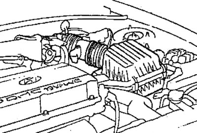
- d) Remove the air flow sensor from the air intake hose.
Caution: Do not pull the air flow sensor by the wiring.
5. Disconnect the air intake hose from the throttle body.
6. Disconnect the accelerator pedal cable.
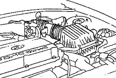
7. Disconnect the cooling system hoses from the throttle body.
8. Disconnect the positive crankcase ventilation hose and the brake booster vacuum hose.
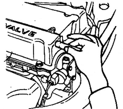
9. Disconnect the vacuum hoses.
10. Remove the protective cover of the injectors.
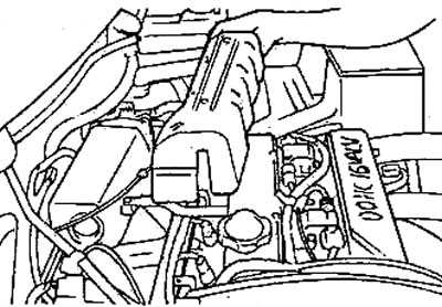
11. Before disconnecting the high-pressure fuel hose from the fuel rail, release any residual pressure from the high-pressure fuel lines to prevent fuel splashing.
12. Disconnect the fuel injector wiring harness connector.
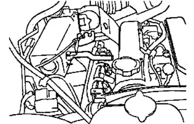
13. Remove the fuel manifold together with the injectors.
Caution: Be careful not to drop the injectors when removing the fuel rail.
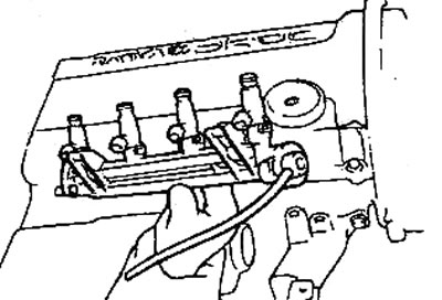
14. Unscrew the intake manifold bracket.
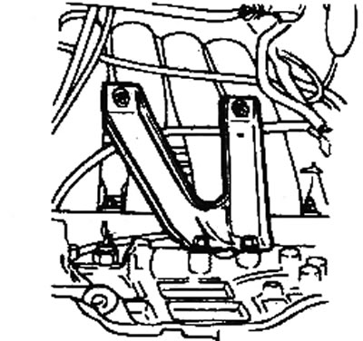
15. Remove the intake manifold.
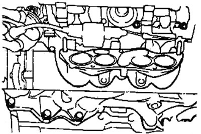
16. Remove the center cover from the cylinder head and the high-tension spark plug wires.
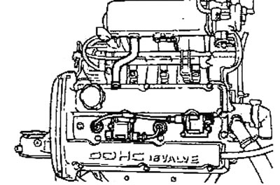
17. Disconnect the wiring connectors and wiring clamps from the cylinder head and intake manifold.
18. Remove the timing belt (see section "Timing Belt Replacement").
19. Remove the cylinder head cover and camshaft position sensor.
20. Loosen the mounting bolts and remove the camshaft sprockets.
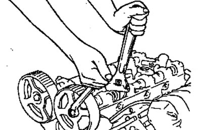
21. Loosen the camshaft bearing cap mounting bolts. Remove the bearing caps, camshafts, valve rocker arms and hydraulic compensators.
Attention: Loosen the bearing cap mounting bolts gradually, in several steps, to avoid deformation of the camshaft.
22. Remove the exhaust manifold heat shield.
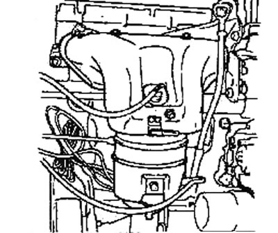
23. Remove the exhaust manifold.
24. Remove the exhaust manifold gasket.
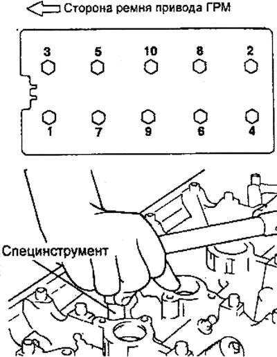
25. Using a special tool, unscrew the cylinder head mounting bolts in 2-3 steps in the order shown in the figure.
Installation
Installation of parts is carried out in the reverse order of removal. When installing parts, pay attention to the following operations.
1. Installing the cylinder head and cylinder head gasket.
- a) Clean the mating surfaces under the gasket on the cylinder head and cylinder block.
- b) Check that the cylinder head gasket identification marks match the technical data.
- c) Install the cylinder head gasket on the cylinder block with the identification mark facing up (towards the cylinder head).
Note: Before installing the cylinder head bolts, measure their length.
- Maximum bolt length: 99.4 mm
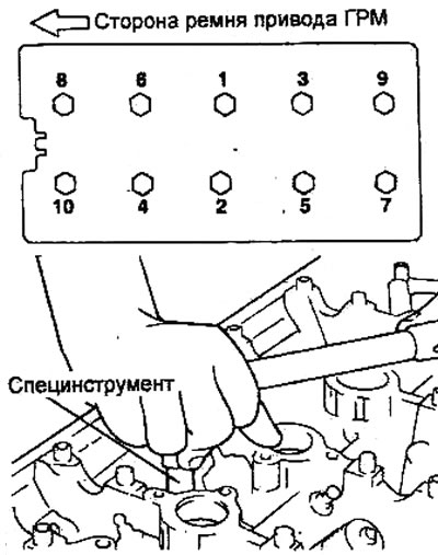
- d) If the cylinder head mounting bolts have been replaced, then in the order shown in the figure, pre-tighten them to a torque of 20 Nm, then turn them to an angle of 180-184°, then completely loosen them in 2-3 steps in the reverse order.
- d) If the cylinder head gasket or cylinder head has been replaced, in the order shown in the figure, pre-tighten the bolts to 63 Nm, then completely loosen in 2-3 steps in the reverse order.
- e) Tighten the cylinder head bolts in the order shown in the figure as follows:
- First tighten all bolts to 20 Nm.
- Tighten all mounting bolts to an angle of 90-94°.
- Finally tighten all mounting bolts to an angle of 90-94°.
2. Installing manifold gaskets.
Caution: Replace the manifold gasket with a new one before reinstalling.
3. Installing the camshafts, camshaft oil seal, camshaft sprocket and cylinder head cover.
- a) Install the camshafts into the cylinder head. Do not install the valve rocker arms.
Note:
- Apply engine oil to the camshaft journals and camshaft lobes.
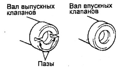
- On the rear end of the exhaust camshaft there are grooves for installing the camshaft position sensor.
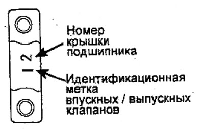
- b) Install the camshaft bearing caps. The identification marks on the bearing caps are designed to identify the installation location of the cap (inlet/exhaust side).
- I: Intake camshaft.
- E: exhaust camshaft.
- c) Check the smooth rotation of the camshafts by hand. After checking, remove the bearing caps and install the valve rocker arms.
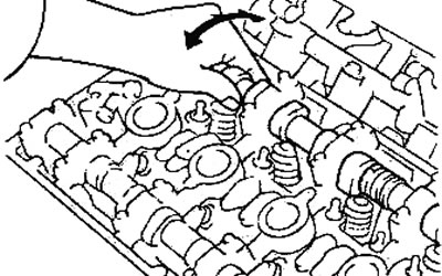
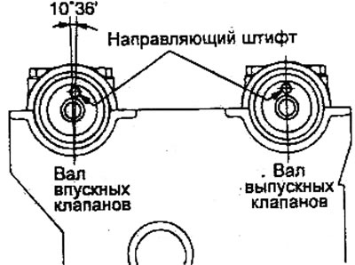
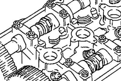
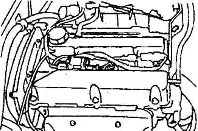
- d) Install the camshafts so that the guide pins are positioned as shown in the figure.
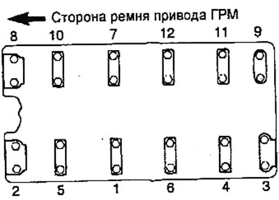
- d) Tighten the camshaft bearing cap bolts to the specified torque in two or three steps and in the sequence shown in the figure.
Note: Check that the valve rocker arm is properly installed on the hydraulic lifter and valve stem.
- Tightening torque: 19-21 Nm
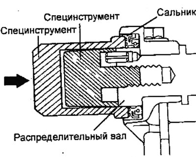
- e) Using a special tool (camshaft seal installation mandrel, guide), press in the camshaft seal. Make sure that the working edge and the outer surface of the camshaft seal are lubricated with engine oil. Place the seal on the camshaft from the side of the timing belt sprocket, then use a hammer to install the seal until it stops.
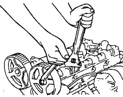
- g) Install the camshaft sprockets and tighten the mounting bolts to the specified torque.
- Tightening torque: 80-100 Nm
 |
 |
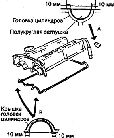
- h) Install the cylinder head cover. Apply sealant as shown in the figure.
Sealant:
- Area "A": Three Bond No.1212D or equivalent
- Area "B": Three Bond No.1212D or equivalent
- i) Tighten the cylinder head cover mounting bolts "A".
- Tightening torque: 8-10 Nm
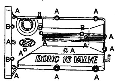
- j) Install spark plugs and ignition coils. Connect spark plug high-tension wires and install center cap. Tighten bolts "B".
- Tightening torque: 4-5 Nm
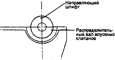
- l) Position the intake camshaft sprocket guide pin as shown in the figure.
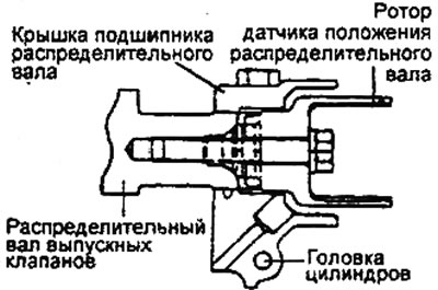
- m) Install the camshaft position sensor rotor onto the exhaust camshaft, then install the camshaft position sensor mounting bracket. Tighten the sensor mounting bolt.
- Tightening torque: 10-13 Nm
4. Install the timing belt (see section "Timing Belt Replacement").
5. After all parts are installed, fill the coolant. Start the engine and check for leaks.