
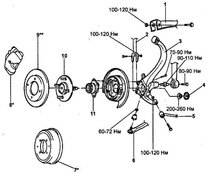
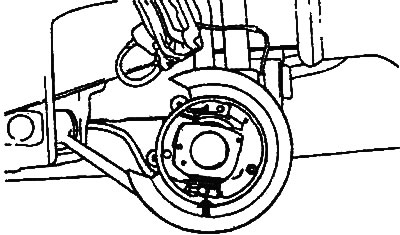
Rear wheel knuckle and hub.
1 - upper arm of the rear suspension, 2 - longitudinal rod of the rear suspension, 3 - knuckle, 4 -, 5 - transverse rod of the rear suspension, 6 - transverse arm of the rear suspension, 7 - brake drum, 8 - caliper, 9 - brake disc, 10 - rear wheel hub, 11 - hub bearing housing, 12 - drum* / parking** brake.
Note:
- * - for models with drum brakes,
- ** - for models with disc brakes.
Removal
1. Make sure the parking brake is not applied.
2. Jack up the car, unscrew the bolts and remove the rear wheel.
- Tightening torque: 90-110 Nm
3. Remove the wheel speed sensor (see chapter "Brake system").
4. Unscrew the bolt and, having disconnected the brake caliper from the knuckle, hang it on the wire.
- Tightening torque: 69-85 Nm
5. Remove the brake disc.
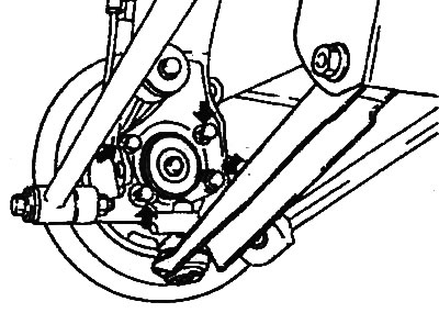
6. Unscrew the four bolts and remove the rear wheel hub assembly with the bearing housing.
- Tightening torque: 70-90 Nm
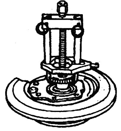
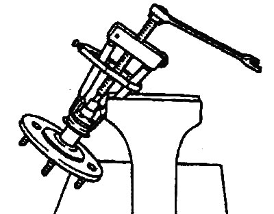
7. Using the special tool, remove the wheel speed sensor rotor.
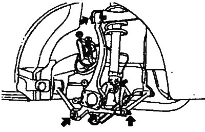
8. Unscrew the stud, unscrew the nuts, remove the bolts and remove the knuckle.
Tightening torque:
- studs: 90-110 Nm
- upper arm and rear suspension rod mounting nuts: 100-120 Nm
- rear suspension lower arm mounting nuts: 60-72 Nm
Disassembly
1. Unscrew the flange nut.
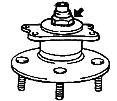
2. Using a special tool, remove the hub from the bearing housing.
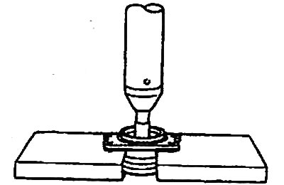
3. Using a special tool, remove the inner bearing race from the hub.
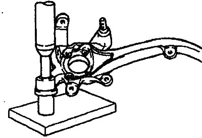
4. Using special tools, remove the two bushings from the knuckle.
Examination
1. Check the bearing housing for wear and damage.
2. Make sure that there is no damage to the teeth of the wheel speed sensor rotor.
3. Check the inner surface of the hub for burrs.
4. Check that there is no damage to the fist.
Assembly
The installation of the rear wheel hub and knuckle is carried out in the reverse order of removal; the tightening torque of the nut is indicated in the text of the description of the disassembly procedure and in the assembly drawing "Knuckle and rear wheel hub".
Installation
1. The rear wheel hub and knuckle are installed in the reverse order of removal; the tightening torques for the bolts and nuts are specified in the text describing the removal procedure and in the assembly drawing "Knuckle and rear wheel hub".
2. If necessary, change the position of the brake pads by turning the adjuster.
3. Measure the breaking torque of the hub bearing as shown in the figure.
(This publication is based on information from the portal HyundaiBook.ru)
- Breakaway torque: 28 N or less
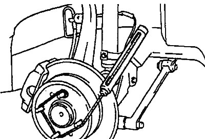
4. Measure the axial runout of the wheel hub as shown in the figure.
- Axial runout: 0.008 mm