
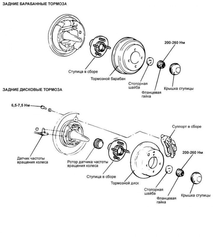
Fig. 3.150. Rear wheel hub
Removal
Caution: On vehicles with ABS, remove the rear wheel speed sensor.
Caution: Be careful when removing the wheel speed sensor from the bracket to avoid damaging the sensor pole piece on the rotor teeth or other parts.
Remove the disc brake caliper and hang it to the side with wire.
Remove the brake disc.
Remove the hub cover, unscrew the hub bearing mounting nut and remove the lock washer.
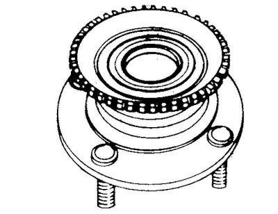
Fig. 3.151. Removing the hub assembly
Remove the hub assembly (Fig. 3.151).
Caution! The rear wheel hub bearing assembly cannot be removed.
Warning! Be careful not to scratch or damage the teeth of the wheel speed sensor rotor. Do not drop the rotor. Chipping of the sensor rotor teeth will cause deformation of the rotor and, as a result, the impossibility of correctly determining the wheel speed and disruption of the ABS system as a whole.
Examination
Check the seal for cracks or damage.
Check the wheel hub bearing for wear or damage.
Check for chipping of the wheel speed sensor rotor teeth.
Check the rear wheel knuckle for cracks.
Installation
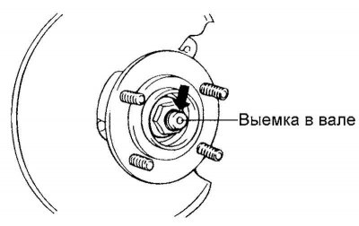
Fig. 3.152. Caulking a flange nut
After tightening the flange nut, calk the edge of the nut into the recess in the rear wheel cam shaft (Fig. 3.152).
Caution: Replace the flange nut with a new one after removing.
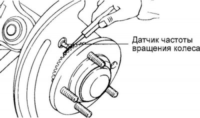
Fig. 3.153. Wheel speed sensor
For vehicles with ABS, install the rear wheel speed sensor. To do this, insert a flat feeler gauge into the gap between the pole piece of the wheel speed sensor and the sensor rotor tooth. Secure the sensor so that the gap between the pole piece of the sensor and the rotor tooth (along the entire circumference) is within the nominal value (Fig. 3.153).
Nominal gap size: 0.2–1.3 mm.
Install the wheel hub cap.